Toyota Venza: Components
COMPONENTS
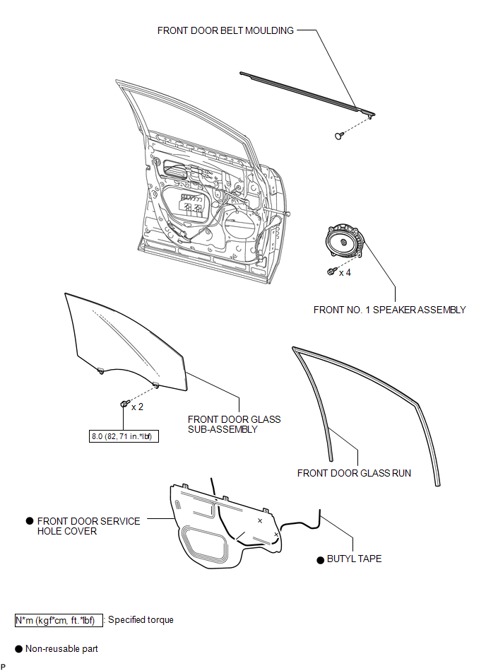
ILLUSTRATION
.png)
ILLUSTRATION

 Installation
INSTALLATION
PROCEDURE
1. INSTALL FRONT DOOR BELT MOULDING
(a) Engage the 5 claws to install the front door belt moulding.
(b) Install the ...
Other materials about Toyota Venza:
Test Mode Procedure
TEST MODE PROCEDURE
1. WARNING LIGHT AND INDICATOR LIGHT INITIAL CHECK
(a) Release the parking brake.
NOTICE:
Before releasing the parking brake, move the shift lever to P for safety.
HINT:
When the parking brake is applied or the brake fluid level is lo ...
Removal
REMOVAL
PROCEDURE
1. DISCONNECT CABLE FROM NEGATIVE BATTERY TERMINAL
CAUTION:
Wait at least 90 seconds after disconnecting the cable from the negative (-)
battery terminal to disable the SRS system.
NOTICE:
When disconnecting the cable, some systems ne ...
Unlock Position Sensor Signal Circuit
DESCRIPTION
The unlock position sensor is one of the components comprising the steering lock
ECU (steering lock actuator assembly). The sensor switch contact closes when the
steering lock is released. The steering lock release signal is then sent to the
...

0.1727