Toyota Venza: Removal
REMOVAL
PROCEDURE
1. DISCONNECT CABLE FROM NEGATIVE BATTERY TERMINAL
CAUTION:
Wait at least 90 seconds after disconnecting the cable from the negative (-) battery terminal to disable the SRS system.
NOTICE:
When disconnecting the cable, some systems need to be initialized after the cable
is reconnected (See page .gif) ).
).
2. REMOVE FRONT DOOR INSIDE HANDLE BEZEL PLUG
3. REMOVE POWER WINDOW REGULATOR MASTER SWITCH ASSEMBLY WITH FRONT DOOR ARMREST BASE PANEL (for Driver Side)
4. REMOVE POWER WINDOW REGULATOR SWITCH ASSEMBLY WITH FRONT DOOR ARMREST BASE PANEL (for Front Passenger Side)
5. REMOVE COURTESY LIGHT ASSEMBLY
6. REMOVE FRONT DOOR TRIM BOARD SUB-ASSEMBLY
7. REMOVE FRONT DOOR INSIDE HANDLE SUB-ASSEMBLY
8. REMOVE DOOR SIDE AIRBAG SENSOR
9. REMOVE FRONT NO. 1 SPEAKER ASSEMBLY
10. REMOVE FRONT DOOR SERVICE HOLE COVER
11. REMOVE FRONT DOOR GLASS SUB-ASSEMBLY
12. REMOVE FRONT DOOR GLASS RUN
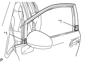
13. REMOVE FRONT DOOR BELT MOULDING
|
(a) Put protective tape around the front door belt moulding. Text in Illustration
|
|
|
(b) Using a clip remover, remove the clip. |
|
.png)
(c) Using a screwdriver, disengage the 5 claws and remove the front door belt moulding.
 Installation
INSTALLATION
PROCEDURE
1. INSTALL FRONT DOOR BELT MOULDING
(a) Engage the 5 claws to install the front door belt moulding.
(b) Install the ...

Other materials about Toyota Venza:
Lost Communication with ECM / PCM "A" (U0100-U0142,U0155)
DESCRIPTION
These DTCs are stored when the clearance warning ECU assembly cannot receive
and recognize several signals via the CAN communication system.
DTC No.
DTC Detection Condition
Trouble Area
U0100
...
Ambient Temperature Sensor
Components
COMPONENTS
ILLUSTRATION
Inspection
INSPECTION
PROCEDURE
1. INSPECT AMBIENT TEMPERATURE SENSOR
(a) Measure the resistance according to the value(s) in the table below.
Standard Resistance:
Tester Connection
C ...
Diagnosis System
DIAGNOSIS SYSTEM
1. DESCRIPTION
(a) The transponder key ECU assembly controls the vehicle's immobiliser system
functions. Immobiliser system data and Diagnostic Trouble Code (DTC) can be read
through the vehicle's Data Link Connector 3 (DLC3).
I ...

0.1398