Toyota Venza: Installation
INSTALLATION
PROCEDURE
1. INSTALL REAR ENGINE OIL SEAL
(a) Apply MP grease to the lip of a new oil seal.
NOTICE:
- Do not allow foreign matter to contact the lip of the oil seal.
- Do not allow MP grease to contact the dust seal.
|
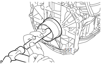
(b) Using SST and a hammer, tap in the oil seal until its surface is flush with the edges of the cylinder block and crankcase. SST: 09223-15030 SST: 09950-70010 09951-07150 NOTICE:
|
|
2. INSTALL DRIVE PLATE AND RING GEAR SUB-ASSEMBLY
|
(a) Using SST, hold the crankshaft. SST: 09213-54015 SST: 09330-00021 HINT: Part number of installation bolt for SST (crankshaft pulley holding tool): 91551-80650 (quantity: 2) |
|
.png)
(b) Clean the bolts and their installation holes.
|
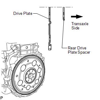
(c) Install the front drive plate spacer. HINT: Align the pin of the front drive plate spacer with the pin hole of the crankshaft. |
|

|
(d) Install the drive plate and rear drive plate spacer to the crankshaft. |
|
|
(e) Apply a few drops of adhesive to 2 or 3 threads of the bolt end. Adhesive: Toyota Genuine Adhesive 1324, Three Bond 1324 or equivalent |
|
.png)
|
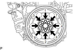
(f) Install and uniformly tighten the 8 bolts in the sequence shown in the illustration. Torque: 98 N·m {999 kgf·cm, 72 ft·lbf} NOTICE: Do not strike or damage the drive plate installation bolts. Be sure to handle them carefully. |
|
3. INSTALL AUTOMATIC TRANSAXLE ASSEMBLY (for 2WD)
When Not Using the Engine Support Bridge: (See page
.gif) )
)
When Using the Engine Support Bridge: (See page
)
4. INSTALL AUTOMATIC TRANSAXLE ASSEMBLY (for AWD)
When Not Using the Engine Support Bridge: (See page
)
When Using the Engine Support Bridge: (See page
)
 Removal
REMOVAL
PROCEDURE
1. REMOVE AUTOMATIC TRANSAXLE ASSEMBLY (for 2WD)
When Not Using the Engine Support Bridge: (See page
)
When Using the Engine Support Bridge: (See page
)
2. REMOVE AUTOMATIC ...
 1ar-fe Fuel
...
Other materials about Toyota Venza:
Stereo Component Amplifier Malfunction (B15A3)
DESCRIPTION
This DTC is stored when a malfunction occurs in the stereo component amplifier
assembly.
DTC No.
DTC Detection Condition
Trouble Area
B15A3
When any of the following conditions is met ...
Removal
REMOVAL
PROCEDURE
1. PRECAUTION (w/ Navigation System)
NOTICE:
After turning the ignition switch off, waiting time may be required before disconnecting
the cable from the negative (-) battery terminal. Therefore, make sure to read the
disconnecting the ...
IG2 Signal Malfunction (B2788)
DESCRIPTION
The steering lock ECU (steering lock actuator assembly) receives power from the
IG2 relay. When the voltage value indicated by the IG signal from the certification
ECU (smart key ECU assembly) equals to the voltage that is applied to the steer ...

0.1222