Toyota Venza: Oil Pressure Switch
Components
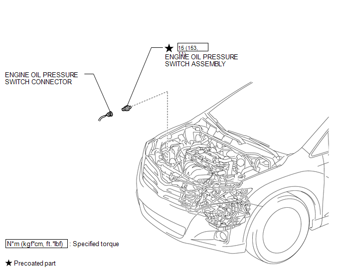
COMPONENTS
ILLUSTRATION
Inspection
INSPECTION
PROCEDURE
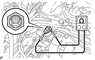
1. INSPECT ENGINE OIL PRESSURE SWITCH ASSEMBLY
(a) Disconnect the oil pressure switch connector.
(b) Start the engine.
|
(c) Measure the resistance according to the value(s) in the table below. Standard Resistance:
If the result is not as specified, replace the oil pressure switch assembly. |
|
Removal
REMOVAL
PROCEDURE
1. REMOVE ENGINE OIL PRESSURE SWITCH ASSEMBLY
|
(a) Disconnect the oil pressure switch connector. |
|
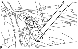
(b) Using a 24 mm deep socket wrench, remove the oil pressure switch.
Installation
INSTALLATION
PROCEDURE
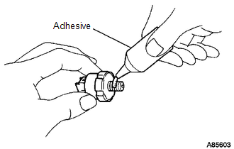
1. INSTALL ENGINE OIL PRESSURE SWITCH ASSEMBLY
|
(a) Apply adhesive to 2 or 3 threads of the oil pressure switch. Adhesive: TOYOTA Genuine Adhesive 1344, Three Bond 1344 or equivalent. NOTICE: Do not let adhesive adhere to the oil hole. |
|
|
(b) Using a 24 mm deep socket wrench, install the oil pressure switch. Torque: 15 N·m {153 kgf·cm, 11 ft·lbf} NOTICE: Do not start the engine within 1 hour of installation. |
|
.png)
(c) Connect the oil pressure switch connector.
2. INSPECT FOR OIL LEAK
.gif)
3. INSPECT ENGINE OIL LEVEL
 Replacement
REPLACEMENT
CAUTION / NOTICE / HINT
CAUTION:
Prolonged and repeated contact with engine oil will result in the removal
of natural oils from the skin, leading to dryness, irritation and ...
 Oil Pump
...
Other materials about Toyota Venza:
Knock Sensor 1 Circuit Low Input (Bank 1 or Single Sensor) (P0327,P0328)
DESCRIPTION
Flat-type knock sensors (non-resonant type) have structures that can detect vibrations
between approximately 5 and 15 kHz.
Knock sensors are fitted onto the engine block to detect engine knocking.
The knock sensor contains a piezoelectric elem ...
Reassembly
REASSEMBLY
CAUTION / NOTICE / HINT
HINT:
Use high-temperature grease to lubricate the bearings, gears and return spring
when assembling the starter.
PROCEDURE
1. INSTALL PLANETARY GEAR
(a) Apply grease to the planetary gears and pin parts of ...
Lost Communication with Rear Airbag Sensor RH (B1632/81,B1633/81,B1642/81,B1692/81,B1693/81)
DESCRIPTION
The side collision sensor RH circuit (to determine deployment of the front seat
side airbag assembly RH and curtain shield airbag assembly RH) is composed of the
center airbag sensor assembly, rear airbag sensor RH and side airbag sensor RH.
...

0.1271