Toyota Venza: Main Body Ecu
Components
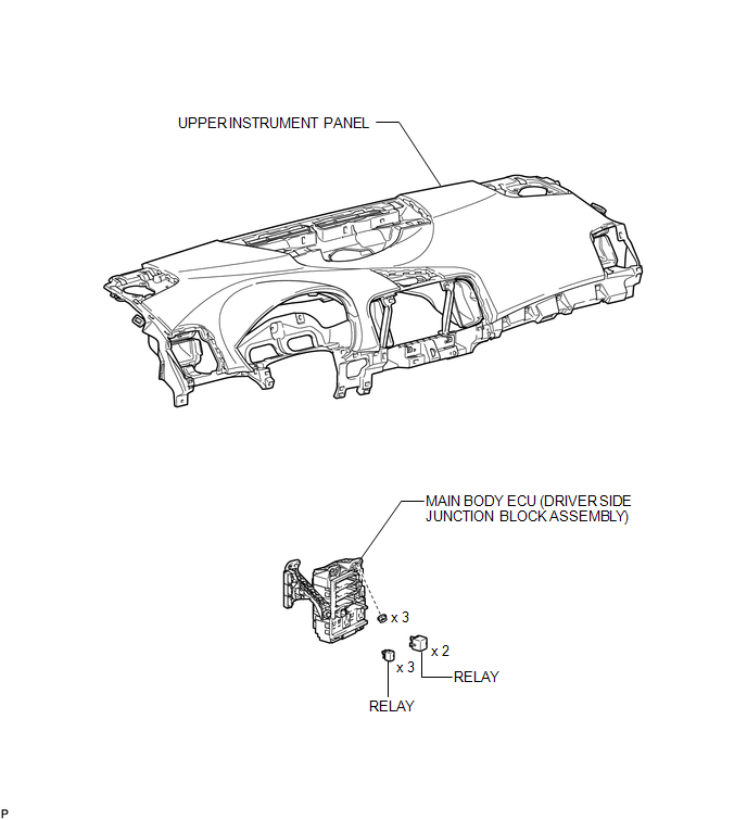
COMPONENTS
ILLUSTRATION
Removal
REMOVAL
PROCEDURE
1. REMOVE UPPER INSTRUMENT PANEL
HINT:
Refer to the procedure up to Remove Upper Instrument Panel Sub-assembly (See
page .gif) ).
).
2. REMOVE MAIN BODY ECU (DRIVER SIDE JUNCTION BLOCK ASSEMBLY)
|
(a) Disconnect the 4 connectors. |
|
|
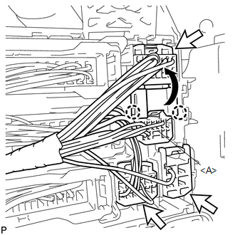
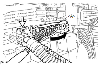
(b) Disengage the 2 claws and disconnect the connector <A> as shown in the illustration. |
|
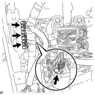
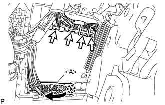
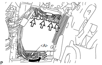
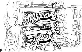
(c) Disconnect the 3 connectors.
|
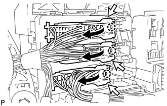
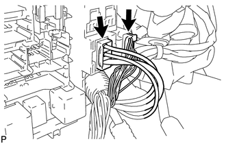
(d) Disconnect the 3 connectors as shown in the illustration. |
|
|
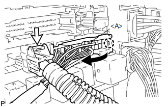
(e) Disconnect the connector <A> as shown in the illustration. |
|
(f) Disconnect the connector.
|
(g) Disconnect the 2 connectors. |
|
|
(h) Remove the 3 nuts. |
|
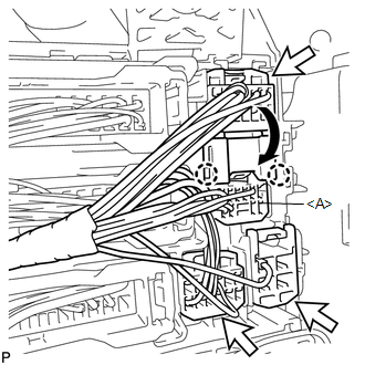
(i) Disengage the 2 claws.
|
(j) Disconnect the connector <A> as shown in the illustration. |
|
(k) Disconnect the 4 connectors and remove the main body ECU (driver side junction block assembly).
|
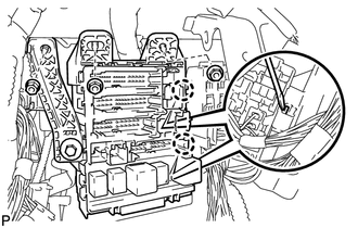
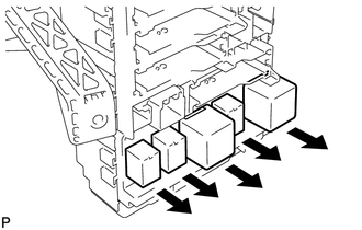
(l) Remove the 5 relays. |
|
Installation
INSTALLATION
PROCEDURE
1. INSTALL MAIN BODY ECU (DRIVER SIDE JUNCTION BLOCK ASSEMBLY)
|
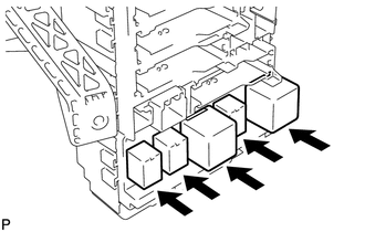
(a) Install the 5 relays. |
|
|
(b) Connect the 4 connectors. |
|
(c) Connect the connector <A> as shown in the illustration.
NOTICE:
Be sure to engage each connector securely.
|
(d) Engage the 2 claws. |
|
.png)
(e) Install the 3 nuts and install the main body ECU (driver side junction block assembly).
|
(f) Connect the 2 connectors. NOTICE: Be sure to engage the connector securely. |
|
.png)
|
(g) Connect the connector <A> as shown in the illustration. NOTICE: Be sure to engage the connector securely. |
|
(h) Connect the connector.
NOTICE:
Be sure to engage each connector securely.
|
(i) Connect the 3 connectors as shown in the illustration. NOTICE: Be sure to engage each connector securely. |
|
|
(j) Engage the 2 claws to connect the connector <A> as shown in the illustration. NOTICE: Be sure to engage the connector securely. |
|
(k) Connect the 3 connectors.
NOTICE:
Be sure to engage each connector securely.
|
(l) Connect the 4 connectors. NOTICE: Be sure to engage each connector securely. |
|
.png)
2. INSTALL UPPER INSTRUMENT PANEL
HINT:
Refer to the procedure from Install Upper Instrument Panel Sub-assembly (See
page .gif) ).
).
 Installation
INSTALLATION
PROCEDURE
1. INSTALL POWER DISTRIBUTION
(a) Connect the 3 connectors.
(b) Engage the 2 claws to temporarily instal ...
 Power Management Control Ecu
Components
COMPONENTS
ILLUSTRATION
Removal
REMOVAL
PROCEDURE
1. REMOVE FRONT DOOR SCUFF PLATE RH
2. REMOVE COWL SIDE TRIM SUB-ASSEMBLY RH
3. REMOVE NO. 2 INSTRUMENT PANEL UNDER COV ...
Other materials about Toyota Venza:
Problem Symptoms Table
PROBLEM SYMPTOMS TABLE
HINT:
Use the table below to help determine the cause of problem symptoms.
If multiple suspected areas are listed, the potential causes of the symptoms
are listed in order of probability in the "Suspected Area" ...
Transmission Range Sensor Circuit Malfunction (PRNDL Input) (P0705)
DESCRIPTION
The park/neutral position switch detects the shift lever position and sends signals
to the TCM.
DTC No.
DTC Detection Condition
Trouble Area
P0705
(A) Any 2 or more signals of the fol ...
Indicators and warning lights
The indicator and warning lights on the instrument cluster and center panel
inform the driver of the status of the vehicle’s various systems.
For the purpose of explanation, the following illustration displays all indicators
and warning lights illuminat ...

0.1612