Toyota Venza: Removal
REMOVAL
PROCEDURE
1. REMOVE AUTOMATIC TRANSAXLE ASSEMBLY (for 2WD)
When Not Using the Engine Support Bridge: (See page
.gif) )
)
When Using the Engine Support Bridge: (See page
)
2. REMOVE AUTOMATIC TRANSAXLE ASSEMBLY (for AWD)
When Not Using the Engine Support Bridge: (See page
)
When Using the Engine Support Bridge: (See page
)
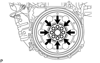
3. REMOVE DRIVE PLATE AND RING GEAR SUB-ASSEMBLY
|
(a) Using SST, hold the crankshaft pulley. SST: 09213-54015 SST: 09330-00021 HINT: Part number of installation bolt for SST (crankshaft pulley holding tool): 91551-80650 (quantity: 2) |
|
.png)
|
(b) Remove the 8 bolts, front drive plate spacer, drive plate and ring gear sub-assembly, and rear drive plate spacer. |
|
4. REMOVE REAR ENGINE OIL SEAL
|
(a) Using a knife, cut off the lip of the oil seal. Text in Illustration
|
|
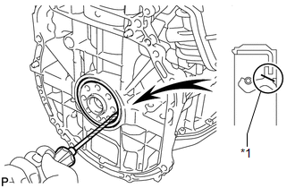
(b) Using a screwdriver, pry out the oil seal.
HINT:
Tape the screwdriver tip before use.
NOTICE:
Do not damage the surface of the oil seal press fit hole or the crankshaft.
 Components
COMPONENTS
ILLUSTRATION
...
 Installation
INSTALLATION
PROCEDURE
1. INSTALL REAR ENGINE OIL SEAL
(a) Apply MP grease to the lip of a new oil seal.
NOTICE:
Do not allow foreign matter to contact the lip of the oil seal.
Do not ...
Other materials about Toyota Venza:
Removal
REMOVAL
CAUTION / NOTICE / HINT
NOTICE:
Make sure to select FACE mode before disconnecting the cable from the negative
(-) battery terminal.
PROCEDURE
1. RECOVER REFRIGERANT FROM REFRIGERATION SYSTEM
2. REMOVE WINDSHIELD WIPER MOTOR AND LINK ASSEMBL ...
System Description
SYSTEM DESCRIPTION
1. GENERAL
The windshield deicer system's thin heater wires are attached to the inside of
the front window and deice the window surface quickly. The indicator light illuminates
while the system is operating. The system automaticall ...
No Answer-Back
DESCRIPTION
In some cases, wireless door lock control functions are normal but the hazard
warning light and/or wireless door lock buzzer answer-back function(s) does not
operate. In such cases, the main body ECU (driver side junction block assembly)
haz ...

0.1574