Toyota Venza: Reassembly
REASSEMBLY
PROCEDURE
1. INSTALL FRONT OIL PUMP OIL SEAL
|
(a) Using SST and a hammer, install a new oil seal to the oil pump body. SST: 09350-32014 09351-32140 Oil seal driven in depth: -0.25 to 0.25 mm (-0.00984 to 0.00984 in.) |
|
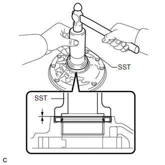
(b) Coat the lip of the oil seal with MP grease.
2. INSTALL FRONT OIL PUMP BODY O-RING
|
(a) Coat a new O-ring with ATF and install it to the oil pump body. NOTICE: Ensure that the O-ring is not twisted. |
|
.png)
3. INSTALL FRONT OIL PUMP DRIVEN GEAR
|
(a) Coat the front oil pump driven gear with ATF and install it to the oil pump body with the marked side up. |
|
.png)
4. INSTALL FRONT OIL PUMP DRIVE GEAR
|
(a) Coat the front oil pump drive gear with ATF, and install it to the oil pump body with the marked side up. |
|
.png)
5. INSTALL STATOR SHAFT ASSEMBLY
|
(a) Align each knock pin of the stator shaft with the holes in the oil pump body and install the stator shaft to the oil pump body. |
|
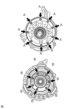
(b) Using a "TORX" socket (T30), install the 16 bolts.
Torque:
9.3 N·m {95 kgf·cm, 82 in·lbf}
| - | Bolt Length |
|---|---|
| Bolt A |
14 mm (0.551 in.) |
| Bolt B |
26 mm (1.02 in.) |
6. INSPECT FRONT OIL PUMP AND GEAR BODY SUB-ASSEMBLY
.gif)
 Inspection
INSPECTION
PROCEDURE
1. INSPECT FRONT OIL PUMP AND GEAR BODY SUB-ASSEMBLY
(a) Turn the drive gear with 2 screwdrivers and make sure that it rotates
smoothly.
NOTICE:
Be careful ...

Other materials about Toyota Venza:
Front passenger occupant classification system
Your vehicle is equipped with a front passenger occupant classification system.
This system detects the conditions of the front passenger seat and activates or
deactivates the devices for front passenger.
1. SRS warning light
2. Front passenger’s sea ...
Poor Sound Quality in All Modes (Low Volume)
PROCEDURE
1.
CHECK AUDIO SETTINGS
(a) Set treble, middle and bass to the initial values and check that the sound
is normal.
OK:
The sound returns to normal.
HINT:
Sound quality adjustment measures vary according to the ...
Data List / Active Test
DATA LIST / ACTIVE TEST
1. DATA LIST
HINT:
Using the Techstream to read the Data List allows the values or states of switches,
sensors, actuators and other items to be read without removing any parts. This non-intrusive
inspection can be very useful bec ...

0.1554