Toyota Venza: ACC Monitor Malfunction (B2274)
DESCRIPTION
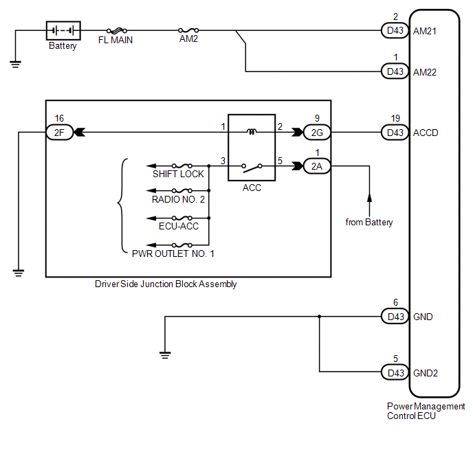
This DTC is stored when there is a problem in the ACC output circuit. The ACC circuit is the circuit that goes from inside the power management control ECU to the ACC relay.
|
DTC No. |
DTC Detection Condition |
Trouble Area |
|---|---|---|
|
B2274 |
The ACC relay actuation circuit inside the power management control ECU or other related circuit is malfunctioning. |
|
WIRING DIAGRAM
CAUTION / NOTICE / HINT
NOTICE:
- When the power management control ECU is replaced with a new one and the cable from the negative (-) battery terminal is connected, the power source mode becomes the on (IG) mode. When the battery is removed and reinstalled, the power source mode that was selected when the battery was removed is restored.
- Inspect the fuses for circuits related to this system before performing the following inspection procedure.
PROCEDURE
|
1. |
CHECK HARNESS AND CONNECTOR (BATTERY - POWER MANAGEMENT CONTROL ECU) |
.gif)
| NG | .gif) |
REPAIR OR REPLACE HARNESS OR CONNECTOR (BATTERY - POWER MANAGEMENT CONTROL ECU) |
|
.gif)
|
2. |
CHECK HARNESS AND CONNECTOR (POWER MANAGEMENT CONTROL ECU - BODY GROUND) |
| NG | |
REPAIR OR REPLACE HARNESS OR CONNECTOR (POWER MANAGEMENT CONTROL ECU - BODY GROUND) |
|
|
3. |
CHECK HARNESS AND CONNECTOR |
(a) Disconnect the 2G connector from the main body ECU (driver side junction block assembly).
(b) Measure the resistance according to the value(s) in the table below.
Standard Resistance:
|
Tester Connection |
Condition |
Specified Condition |
|---|---|---|
|
D43-19 (ACCD) - 2G-9 |
Always |
Below 1 Ω |
|
D43-19 (ACCD) - Body ground |
Always |
10 kΩ or higher |
|
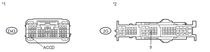
*1 |
Front view of wire harness connector (to Power Management Control ECU) |
*2 |
Front view of wire harness connectors (to Main Body ECU (Driver Side Junction Block Assembly)) |
| NG | |
REPAIR OR REPLACE HARNESS OR CONNECTOR |
|
|
4. |
CHECK HARNESS AND CONNECTOR |
| NG | |
REPAIR OR REPLACE HARNESS OR CONNECTOR |
|
|
5. |
INSPECT ACC RELAY |
|
(a) Remove the ACC relay from the main body ECU (driver side junction block assembly). |
|
.png)
(b) Measure the resistance according to the value(s) in the table below.
Standard Resistance:
|
Tester Connection |
Condition |
Specified Condition |
|---|---|---|
|
1 - 2 |
Always |
93.8 to 136.4 Ω |
|
3 - 5 |
When battery voltage is not applied to terminals 1 and 2 |
10 kΩ or higher |
|
3 - 5 |
When battery voltage is applied to terminals 1 and 2 |
Below 1 Ω |
| NG | |
REPLACE ACC RELAY |
|
|
6. |
INSPECT MAIN BODY ECU (DRIVER SIDE JUNCTION BLOCK ASSEMBLY) |
(a) Remove the main body ECU (driver side junction block assembly) (See page
).
(b) Measure the resistance according to the value(s) in the table below.
Standard Resistance:
|
Tester Connection |
Condition |
Specified Condition |
|---|---|---|
|
2G-9 - ACC relay terminal 2 |
Always |
Below 1 Ω |
|
2G-9 - Body ground |
Always |
10 kΩ or higher |
|
2F-16 - ACC relay terminal 1 |
Always |
Below 1 Ω |
|
2F-16 - Body ground |
Always |
10 kΩ or higher |
|
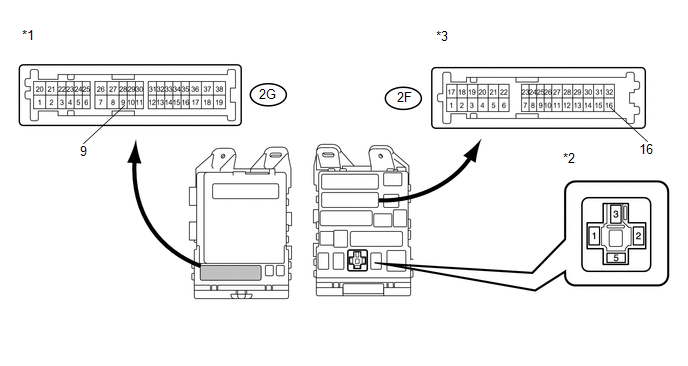
*1 |
Front view of wire harness connector (to Main Body ECU (Driver Side Junction Block Assembly)) |
*3 |
Front view of wire harness connector (to Main Body ECU (Driver Side Junction Block Assembly)) |
|
*2 |
Component without relay connected (ACC Relay Terminal) |
- |
- |
| OK | |
REPLACE POWER MANAGEMENT CONTROL ECU |
| NG | |
REPLACE MAIN BODY ECU (DRIVER SIDE JUNCTION BLOCK ASSEMBLY) |
 Brake Signal Malfunction (B2284)
DESCRIPTION
The power management control ECU receives brake signal information from 2 sources.
It receives a signal from the stop light switch assembly via a direct line, and
a signal from the EC ...
 Engine does not Start
DESCRIPTION
1. ENGINE START SYSTEM FUNCTION
(a) If the engine switch is pressed with the shift lever in P or N and the brake
pedal depressed, the power management control ECU determines that this ...
Other materials about Toyota Venza:
Removal
REMOVAL
PROCEDURE
1. REMOVE NO. 1 ENGINE COVER SUB-ASSEMBLY
2. REMOVE CAMSHAFT TIMING OIL CONTROL VALVE ASSEMBLY (for Exhaust Side)
(a) Disconnect the oil control valve connector.
(b) Remove the ...
Front Brake Flexible Hose
Components
COMPONENTS
ILLUSTRATION
Installation
INSTALLATION
CAUTION / NOTICE / HINT
NOTICE:
Because the left and right hoses are not interchangeable, verify the
part number when installing the flexible hoses.
If the hoses are to b ...
Meter Illumination is Always Dark
DESCRIPTION
In this circuit, the meter CPU receives auto dimmer signals from the main body
ECU (driver side junction block assembly) using the CAN communication system (CAN
No. 1 Bus). When the meter CPU receives an auto dimmer signal, it dims the meter
...

0.1524