Toyota Venza: Inspection
INSPECTION
PROCEDURE
1. INSPECT EVAPORATOR TEMPERATURE SENSOR
(a) Measure the resistance according to the value(s) in the table below.
.png)
Standard Resistance:
|
Tester Connection |
Condition |
Specified Condition |
|---|---|---|
|
1 - 2 |
-10°C (14°F) |
7.30 to 9.10 kΩ |
|
1 - 2 |
-5°C (23°F) |
5.65 to 6.95 kΩ |
|
1 - 2 |
0°C (32°F) |
4.40 to 5.35 kΩ |
|
1 - 2 |
5°C (41°F) |
3.40 to 4.15 kΩ |
|
1 - 2 |
10°C (50°F) |
2.70 to 3.25 kΩ |
|
1 - 2 |
15°C (59°F) |
2.14 to 2.58 kΩ |
|
1 - 2 |
20°C (68°F) |
1.71 to 2.05 kΩ |
|
1 - 2 |
25°C (77°F) |
1.38 to 1.64 kΩ |
|
1 - 2 |
30°C (86°F) |
1.11 to 1.32 kΩ |
NOTICE:
- Hold the sensor only by its connector. Touching the sensor may change the resistance value.
- When measuring, the sensor temperature must be the same as the ambient temperature.
HINT:
As the temperature increases, the resistance decreases (see the graph).
If the resistance is not as specified, replace the evaporator temperature sensor.
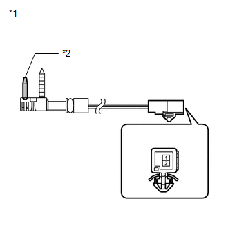
Text in Illustration|
*1 |
Component without harness connected (Evaporator Temperature Sensor) |
|
*2 |
Sensing Portion |
 Removal
REMOVAL
PROCEDURE
1. REMOVE AIR CONDITIONING UNIT ASSEMBLY
(See page )
2. REMOVE NO. 1 FINISH PANEL MOUNTING BRACKET
3. REMOVE NO. 2 FINISH PANEL MOUNTING BRACKET
4. REMOVE NO. 3 AIR DUCT ...
 Installation
INSTALLATION
PROCEDURE
1. INSTALL NO. 1 COOLER THERMISTOR
(a) Install the No. 1 cooler thermistor as shown in the illustration.
Part
Length
...
Other materials about Toyota Venza:
Dtc Check / Clear
DTC CHECK / CLEAR
NOTICE:
When the diagnosis system is changed from normal mode to check mode or vice versa,
all DTCs and freeze frame data recorded in normal mode are cleared. Before changing
modes, always check and make a note of DTCs and freeze frame ...
Blind Spot Mirrors
The Blind Spot Mirrors increase the view of surrounding area to assist the driver
when checking surrounding area before changing lanes.
1. Blind Spot Mirror field of view
2. Main mirror field of view
- Mirror angle can be adjusted when
►V ...
Voice Recognition Microphone Disconnected (B1579)
DESCRIPTION
The radio and display receiver assembly and inner rear view mirror assembly (amplifier
microphone assembly) are connected to each other using the microphone connection
detection signal lines.
This DTC is stored when a microphone connection de ...

0.1266