Toyota Venza: Removal
REMOVAL
PROCEDURE
1. REMOVE AIR CONDITIONING UNIT ASSEMBLY
(See page .gif) )
)
2. REMOVE NO. 1 FINISH PANEL MOUNTING BRACKET
3. REMOVE NO. 2 FINISH PANEL MOUNTING BRACKET
4. REMOVE NO. 3 AIR DUCT SUB-ASSEMBLY
5. REMOVE NO. 2 AIR DUCT SUB-ASSEMBLY
6. REMOVE AIR CONDITIONING HARNESS ASSEMBLY
7. REMOVE COOLER EXPANSION VALVE
8. REMOVE BLOWER ASSEMBLY WITH COOLER EVAPORATOR SUB-ASSEMBLY
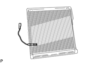
9. REMOVE COOLER EVAPORATOR SUB-ASSEMBLY
10. REMOVE NO. 1 COOLER THERMISTOR
|
(a) Remove the No. 1 cooler thermistor. |
|
 Components
COMPONENTS
ILLUSTRATION
ILLUSTRATION
...
 Inspection
INSPECTION
PROCEDURE
1. INSPECT EVAPORATOR TEMPERATURE SENSOR
(a) Measure the resistance according to the value(s) in the table below.
Standard Resistance:
Tester Connection
...
Other materials about Toyota Venza:
Removal
REMOVAL
CAUTION / NOTICE / HINT
HINT:
Use the same procedure for the LH side and RH side.
The following procedure listed below is for the LH side.
PROCEDURE
1. REMOVE REAR WHEEL
2. SEPARATE REAR SPEED SENSOR
3. REMOVE REAR AXLE SHAF ...
Terminals Of Ecu
TERMINALS OF ECU
1. CHECK MAIN BODY ECU (DRIVER SIDE JUNCTION BLOCK ASSEMBLY)
(a) Disconnect the 2A, 2C and 2F main body ECU (driver side junction block assembly)
connectors.
(b) Measure the voltage and resistance according to the value(s) in the table ...
Removal
REMOVAL
PROCEDURE
1. REMOVE REAR DOOR SCUFF PLATE RH
HINT:
Use the same procedure for the RH side and LH side (See page
).
2. DISCONNECT REAR DOOR OPENING TRIM WEATHERSTRIP RH
HINT:
Use the same procedure for the RH side and LH side (See page
).
3. ...

0.1544