Toyota Venza: Installation
INSTALLATION
PROCEDURE
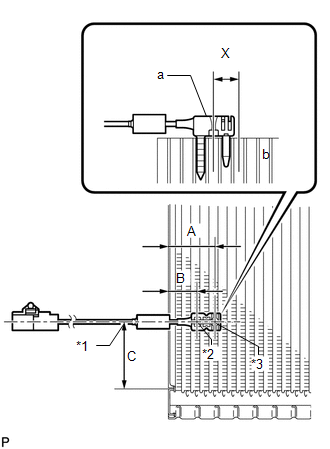
1. INSTALL NO. 1 COOLER THERMISTOR
|
(a) Install the No. 1 cooler thermistor as shown in the illustration.
NOTICE:
|
|
|||||||||||||||||||
2. INSTALL COOLER EVAPORATOR SUB-ASSEMBLY
.gif)
3. INSTALL BLOWER ASSEMBLY WITH COOLER EVAPORATOR SUB-ASSEMBLY
4. INSTALL COOLER EXPANSION VALVE
5. INSTALL AIR CONDITIONING HARNESS ASSEMBLY
6. INSTALL NO. 2 AIR DUCT SUB-ASSEMBLY
7. INSTALL NO. 3 AIR DUCT SUB-ASSEMBLY
8. INSTALL NO. 2 FINISH PANEL MOUNTING BRACKET
9. INSTALL NO. 1 FINISH PANEL MOUNTING BRACKET
10. INSTALL AIR CONDITIONING UNIT ASSEMBLY
(See page )
 Inspection
INSPECTION
PROCEDURE
1. INSPECT EVAPORATOR TEMPERATURE SENSOR
(a) Measure the resistance according to the value(s) in the table below.
Standard Resistance:
Tester Connection
...
 Refrigerant
...
Other materials about Toyota Venza:
TRAC OFF Indicator Light does not Come ON
DESCRIPTION
The skid control ECU is connected to the combination meter via CAN communication.
WIRING DIAGRAM
Refer to TRAC OFF Indicator Light Remains ON (See page
).
PROCEDURE
1.
CHECK CAN COMMUNICATION SYSTEM
(a) Check ...
Seat Heater System
Precaution
PRECAUTION
1. NOTICE FOR INITIALIZATION
HINT:
When disconnecting the cable from the negative (-) battery terminal, initialize
the following systems after the cable is reconnected.
System Name
See procedure
...
Transmission Range Sensor Circuit Malfunction (PRNDL Input) (P0705)
DESCRIPTION
The park/neutral position switch detects the shift lever position and sends signals
to the TCM.
DTC No.
DTC Detection Condition
Trouble Area
P0705
(A) Any 2 or more signals of the fol ...

0.1348