Toyota Venza: Blind Spot Mirrors
The Blind Spot Mirrors increase the view of surrounding area to assist the driver when checking surrounding area before changing lanes.
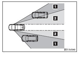
1. Blind Spot Mirror field of view 2. Main mirror field of view
- Mirror angle can be adjusted when
►Vehicles with smart key system The “ENGINE START STOP” switch is in ACCESSORY or IGNITION ON mode.
►Vehicles without smart key system The engine switch is in the “ACC” or “ON” position.
- Linked mirror function when reversing (if equipped)
When the mirror select switch is in the “L” or “R” position, the outside rear view mirrors will automatically angle downwards when the vehicle is reversing in order to give a better view of the ground. To disable this function, move the mirror select switch to the neutral position (between “L” and “R”).
- When the mirrors are fogged up
The outside rear view mirrors can be cleared using the mirror defoggers.
Turn on the rear window defogger to turn on the outside rear view mirror defoggers.
- Automatic adjustment of the mirror angle (if equipped)
The mirror adjustment can be entered into memory and recalled automatically by the driving position memory.
CAUTION
- While driving
Observe the following precautions.
Failing to do so may result in losing control of the vehicle and cause an accident, resulting in death or serious injury.
• Do not adjust the mirrors.
• Do not drive with the mirrors folded back.
• Before driving, be sure to extend mirrors and make an adjustment properly.
- When a mirror is moving
To avoid personal injury and mirror malfunction, be careful not to get your hand caught by the moving mirror.
- When the mirror defoggers are operating
Do not touch the rear view mirror surfaces, as they can become very hot and burn you.
NOTICE
- If ice should jam the mirror
Do not operate the control or scrape the mirror face. Use a spray de-icer to free the mirror.
 Folding back the mirrors (manual type)
Push backward to fold the mirrors. ...

Other materials about Toyota Venza:
Inspection
INSPECTION
PROCEDURE
1. INSPECT EVAPORATOR TEMPERATURE SENSOR
(a) Measure the resistance according to the value(s) in the table below.
Standard Resistance:
Tester Connection
Condition
Specified Condition
...
CD cannot be Inserted or is Ejected Right After Insertion
PROCEDURE
1.
CHECK IF A PROPER CD IS INSERTED
(a) Make sure that the CD is an audio CD or a CD with an MP3, WMA or AAC files,
and that it is not deformed, flawed, stained, deteriorated or otherwise defective.
OK:
Normal C ...
Power outlets
The power outlets can be used for 12V accessories that run on less than 10A.
►Console box
►Front passenger’s side instrument panel
►Luggage compartment
- The power outlets can be used when
►Vehicles with smart key sys ...

0.1256