Toyota Venza: Inspection
INSPECTION
PROCEDURE
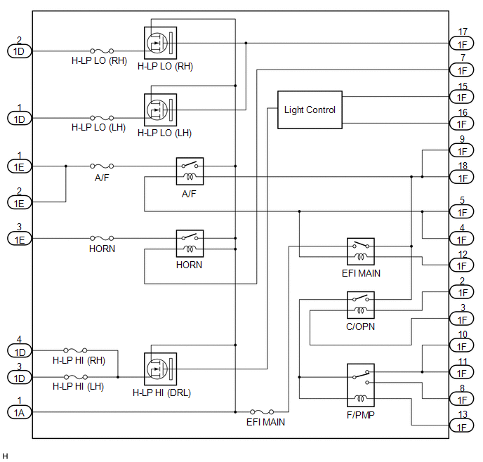
1. INSPECT INTEGRATION RELAY
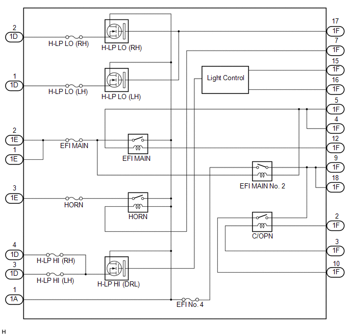
(a) Inner circuit (for 2GR-FE)
|
(1) for EFI MAIN relay
Standard Resistance:
HINT: If the result is not as specified, replace the integration relay. |
|
|
(2) for A/F relay
Standard Resistance:
HINT: If the result is not as specified, replace the integration relay. |
|
|
(3) for F/PMP relay (for AWD)
Standard Resistance:
HINT: If the result is not as specified, replace the integration relay. |
|
|
(4) for C/OPN relay
Standard Resistance:
HINT: If the result is not as specified, replace the integration relay. |
|
|
(5) for HORN relay
Standard Voltage:
HINT: If the result is not as specified, replace the integration relay. |
|
(6) for H-LP LO (LH) relay
- Measure the voltage according to the value(s) in the table below.
Standard Voltage:
|
Tester Connection |
Condition |
Specified Condition |
|---|---|---|
|
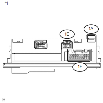
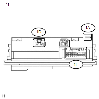
1D-1 - Body ground |
Battery positive (+) - 1A-1 Battery negative (-) - 1F-17 |
11 to 14 V |
|
1A-1 - 1D-1 |
Always |
Below 1 V |
|
*1 |
Component without harness connected (Integration Relay) |
HINT:
If the result is not as specified, replace the integration relay.
(7) for H-LP LO (RH) relay
- Measure the voltage according to the value(s) in the table below.
Standard Voltage:
|
Tester Connection |
Condition |
Specified Condition |
|---|---|---|
|
1D-2 - Body ground |
Battery positive (+) - 1A-1 Battery negative (-) - 1F-17 |
11 to 14 V |
|
1A-1 - 1D-2 |
Always |
Below 1 V |
|
*1 |
Component without harness connected (Integration Relay) |
HINT:
If the result is not as specified, replace the integration relay.
(8) for H-LP HI (DRL) relay
- for Halogen headlight
- Measure the voltage according to the value(s) in the table below.
Standard Voltage:
Tester Connection
Condition
Specified Condition
1A-1 - 1D-3
Always
Below 1 V
1A-1 - 1D-4
Always
Below 1 V
1F-15 - Body ground
Battery positive (+) - 1A-1
Battery negative (-) - 1F-15
Battery negative (-) - 1F-16
11 to 14 V
1F-15 - Body ground
Battery positive (+) - 1A-1
Battery negative (-) - 1F-15
Battery negative (-) - 1F-16
Pulse generation
1F-16 - Body ground
Battery positive (+) - 1A-1
Battery negative (-) - 1F-15
Battery negative (-) - 1F-16
11 to 14 V
1F-16 - Body ground
Battery positive (+) - 1A-1
Battery negative (-) - 1F-15
Battery negative (-) - 1F-16
Pulse generation
- Measure the voltage according to the value(s) in the table below.
- for HID headlight
- Measure the voltage according to the value(s) in the table below.
Standard Voltage:
Tester Connection
Condition
Specified Condition
1A-1 - 1D-3
Always
Below 1 V
1A-1 - 1D-4
Always
Below 1 V
1F-15 - Body ground
Battery positive (+) - 1A-1
Battery negative (-) - 1F-15
Battery negative (-) - 1F-16
Pulse generation
1F-16 - Body ground
Battery positive (+) - 1A-1
Battery negative (-) - 1F-15
Battery negative (-) - 1F-16
Pulse generation
- Measure the voltage according to the value(s) in the table below.
|
*1 |
Component without harness connected (Integration Relay) |
HINT:
If the result is not as specified, replace the integration relay.
(b) Inner circuit (for 1AR-FE)
|
(1) for EFI MAIN No. 2 relay
Standard Resistance:
HINT: If the result is not as specified, replace the integration relay. |
|
|
(2) for EFI MAIN relay
Standard Resistance:
HINT: If the result is not as specified, replace the integration relay. |
|
|
(3) for C/OPN relay
Standard Resistance:
HINT: If the result is not as specified, replace the integration relay. |
|
|
(4) for HORN relay
Standard Voltage:
HINT: If the result is not as specified, replace the integration relay. |
|
(5) for H-LP LO (LH) relay
- Measure the voltage according to the value(s) in the table below.
Standard Voltage:
|
Tester Connection |
Condition |
Specified Condition |
|---|---|---|
|
1D-1 - Body ground |
Battery positive (+) - 1A-1 Battery negative (-) - 1F-17 |
11 to 14 V |
|
1A-1 - 1D-1 |
Always |
Below 1 V |
|
*1 |
Component without harness connected (Integration Relay) |
HINT:
If the result is not as specified, replace the integration relay.
(6) for H-LP LO (RH) relay
- Measure the voltage according to the value(s) in the table below.
Standard Voltage:
|
Tester Connection |
Condition |
Specified Condition |
|---|---|---|
|
1D-2 - Body ground |
Battery positive (+) - 1A-1 Battery negative (-) - 1F-17 |
11 to 14 V |
|
1A-1 - 1D-2 |
Always |
Below 1 V |
|
*1 |
Component without harness connected (Integration Relay) |
HINT:
If the result is not as specified, replace the integration relay.
(7) for H-LP HI (DRL) relay
- for Halogen headlight
- Measure the voltage according to the value(s) in the table below.
Standard Voltage:
Tester Connection
Condition
Specified Condition
1A-1 - 1D-3
Always
Below 1 V
1A-1 - 1D-4
Always
Below 1 V
1F-15 - Body ground
Battery positive (+) - 1A-1
Battery negative (-) - 1F-15
Battery negative (-) - 1F-16
11 to 14 V
1F-15 - Body ground
Battery positive (+) - 1A-1
Battery negative (-) - 1F-15
Battery negative (-) - 1F-16
Pulse generation
1F-16 - Body ground
Battery positive (+) - 1A-1
Battery negative (-) - 1F-15
Battery negative (-) - 1F-16
11 to 14 V
1F-16 - Body ground
Battery positive (+) - 1A-1
Battery negative (-) - 1F-15
Battery negative (-) - 1F-16
Pulse generation
- Measure the voltage according to the value(s) in the table below.
- for HID headlight
- Measure the voltage according to the value(s) in the table below.
Standard Voltage:
Tester Connection
Condition
Specified Condition
1A-1 - 1D-3
Always
Below 1 V
1A-1 - 1D-4
Always
Below 1 V
1F-15 - Body ground
Battery positive (+) - 1A-1
Battery negative (-) - 1F-15
Battery negative (-) - 1F-16
Pulse generation
1F-16 - Body ground
Battery positive (+) - 1A-1
Battery negative (-) - 1F-15
Battery negative (-) - 1F-16
Pulse generation
- Measure the voltage according to the value(s) in the table below.
|
*1 |
Component without harness connected (Integration Relay) |
HINT:
If the result is not as specified, replace the integration relay.
 Components
COMPONENTS
ILLUSTRATION
...
 Removal
REMOVAL
PROCEDURE
1. REMOVE POWER DISTRIBUTION
(a) Remove the bolt.
(b) Disengage the 2 claws and disconnect the power distribution from t ...
Other materials about Toyota Venza:
Certification ECU Communication Stop Mode
DESCRIPTION
Detection Item
Symptom
Trouble Area
Certification ECU Communication Stop Mode
"Smart Access/Smart Key/Wireless Tuner" is not displayed on
"CAN Bus Check&q ...
Data List / Active Test
DATA LIST / ACTIVE TEST
1. DATA LIST
HINT:
Using the Techstream to read the Data List allows the values or states of switches,
sensors, actuators and other items to be read without removing any parts. This non-intrusive
inspection can be very useful bec ...
Removal
REMOVAL
PROCEDURE
1. REMOVE INSTRUMENT PANEL SAFETY PAD ASSEMBLY
(See page )
2. REMOVE NO. 1 ANTENNA CORD SUB-ASSEMBLY
(a) Disengage the 7 clamps and remove the No. 1 antenna cord sub-assembly.
3. REMOVE ROOF HEADLINING ASSEMBLY
(See page )
4. REMO ...

0.1355