Toyota Venza: Removal
REMOVAL
PROCEDURE
1. REMOVE POWER DISTRIBUTION
|
(a) Remove the bolt. |
|
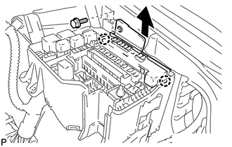
(b) Disengage the 2 claws and disconnect the power distribution from the relay box as shown in the illustration.
|
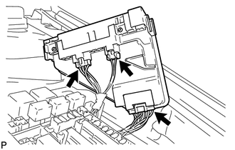
(c) Disconnect the 3 connectors and remove the power distribution. |
|
 Inspection
INSPECTION
PROCEDURE
1. INSPECT INTEGRATION RELAY
(a) Inner circuit (for 2GR-FE)
(1) for EFI MAIN relay
Measure the resistance according to the value(s) in the table
...
 Installation
INSTALLATION
PROCEDURE
1. INSTALL POWER DISTRIBUTION
(a) Connect the 3 connectors.
(b) Engage the 2 claws to temporarily instal ...
Other materials about Toyota Venza:
Terminals Of Ecu
TERMINALS OF ECU
1. CHECK MAIN BODY ECU (DRIVER SIDE JUNCTION BLOCK ASSEMBLY)
(a) Disconnect the 2A and 2C main body ECU (driver side junction block) connectors.
(b) Disconnect the 2F main body ECU connector.
(c) Measure the voltage and resistance accord ...
Intake Air Control Valve Actuator(for Tcv)
Components
COMPONENTS
ILLUSTRATION
Removal
REMOVAL
PROCEDURE
1. REMOVE INTAKE MANIFOLD
(a) Remove the intake manifold (See page ).
2. REMOVE INTAKE AIR CONTROL VALVE ACTUATOR (for TCV)
(a) Remove the 2 bolts, intake air control valve actuator a ...
Navigation Receiver Assembly Power Source Circuit
DESCRIPTION
This is the power source circuit to operate the navigation receiver assembly.
WIRING DIAGRAM
CAUTION / NOTICE / HINT
NOTICE:
Inspect the fuses for circuits related to this system before performing the following
inspection procedure.
PROCE ...

0.1691