Toyota Venza: Components
COMPONENTS
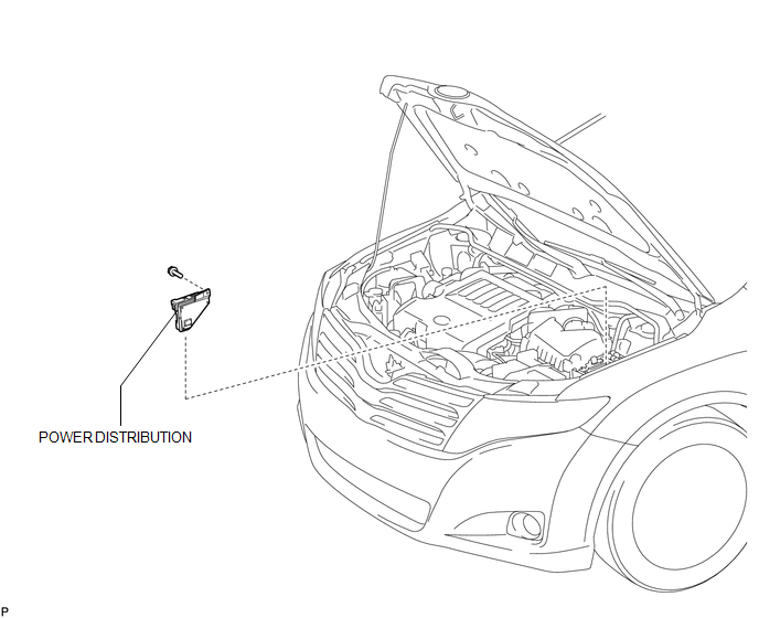
ILLUSTRATION

 Inspection
INSPECTION
PROCEDURE
1. INSPECT INTEGRATION RELAY
(a) Inner circuit (for 2GR-FE)
(1) for EFI MAIN relay
Measure the resistance according to the value(s) in the table
...
Other materials about Toyota Venza:
Input / Turbine Speed Sensor Circuit Malfunction (P0715,P0717)
DESCRIPTION
This sensor detects the rotation speed of the turbine which shows the input revolution
(speed) of the transaxle. By comparing the input turbine speed signal (NT) with
the counter gear speed sensor signal (NC), the TCM detects the shift timing ...
Diagnosis System
DIAGNOSIS SYSTEM
1. CHECK DLC3
(a) Check the DLC3 (See page ).
2. FUNCTION OF SRS WARNING LIGHT
(a) Primary check
(1) Turn the ignition switch off. Wait for at least 2 seconds, then turn the
ignition switch to ON. The SRS warning light comes on for app ...
Removal
REMOVAL
CAUTION / NOTICE / HINT
HINT:
Use the same procedure for the LH side and RH side.
The following procedure is for the LH side.
If the sensor rotor needs to be replaced, replace it together with the
front drive shaft assembly.
...

0.1182