Toyota Venza: On-vehicle Inspection
ON-VEHICLE INSPECTION
PROCEDURE
1. CHECK BATTERY CONDITION
NOTICE:
If the battery is weak or if the engine is difficult to start, perform the following procedure.
(a) Check the battery for damage or deformation. If severe damage, deformation or leakage is found, replace the battery.
(b) Check the electrolyte quantity of each cell.
|
(1) For maintenance-free batteries:
|
|
(c) Check the voltage.
(1) Turn the ignition switch off and turn on the headlights for 20 to 30 seconds. This will remove the surface charge from the battery.
(2) Measure the battery voltage according to the value(s) in the table below.
Standard Voltage:
|
Tester Connection |
Condition |
Specified Condition |
|---|---|---|
|
Positive (+) terminal - Negative (-) terminal |
20°C (68°F) |
12.5 to 12.9 V |
If the result is not as specified, recharge or replace the battery.
2. INSPECT BATTERY TERMINAL
(a) Check that the battery terminals are not loose or corroded.
If a terminal is loose or corroded, tighten or clean the terminal.
Torque:
Positive (+) Battery Terminal :
6.9 N·m {70 kgf·cm, 61 in·lbf}
Negative (-) Battery Terminal :
6.9 N·m {70 kgf·cm, 61 in·lbf}
3. INSPECT FUSES
(a) Measure the resistance of each fuse for the charging system.
HINT:
The fuses shown in the System Diagram are related to the charging system.
Standard Resistance:
Below 1 Ω
- If any of the results is not as specified, replace the fuse(s) as necessary.
4. INSPECT V-RIBBED BELT
.gif)
5. INSPECT GENERATOR WIRING
(a) Visually check the generator wiring.
(1) Check that the wiring is in good condition.
6. CHECK FOR ABNORMAL NOISES
(a) Listen for abnormal noises from the generator.
(1) Check that no abnormal noises are heard from the generator while the engine is running.
7. INSPECT CHARGE WARNING LIGHT CIRCUIT
(a) Turn the ignition switch to ON. Check that the charge warning light comes on.
(b) Start the engine and check that the light goes off.
If the light does not operate as specified, troubleshoot the charge warning light circuit.
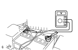
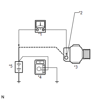
8. INSPECT CHARGING CIRCUIT WITHOUT LOAD
|
(a) Connect a voltmeter and ammeter to the charging circuit as follows. Text in Illustration
(1) Disconnect the wire from terminal B of the generator, and then connect it to the negative (-) lead of the ammeter. (2) Connect the positive (+) lead of the ammeter to terminal B of the generator. (3) Connect the positive (+) lead of the voltmeter to the positive (+) terminal of the battery. (4) Ground the negative (-) lead of the voltmeter. |
|
(b) Check the charging circuit.
(1) Keep the engine speed at 2000 rpm and check the reading on the ammeter and voltmeter.
Standard Current:
10 A or less
Standard Voltage:
13.2 to 14.8 V
If the result is not as specified, repair or replace the generator.
HINT:
If the battery is not fully charged, the ammeter reading will sometimes be more than the standard amperage.
9. INSPECT CHARGING CIRCUIT WITH LOAD
(a) With the engine running at 2000 rpm, turn the high beam headlights on and turn the heater blower switch to the "HI" position.
(b) Check the reading on the ammeter.
Standard Current:
30 A or more
If the ammeter reading is less than the standard amperage, repair or replace the generator.
HINT:
If the battery is fully charged, the indication will sometimes be less than the standard amperage. If this is the case, add more electrical load (operate the wipers, rear window defogger, etc.) and check the reading on the ammeter again.
 System Diagram
SYSTEM DIAGRAM
...
 Problem Symptoms Table
PROBLEM SYMPTOMS TABLE
Use the table below to help determine the cause of problem symptoms.
If multiple suspected areas are listed, the potential causes of the symptoms
are listed in o ...
Other materials about Toyota Venza:
Sound Quality is Bad Only when CD is Played (Volume is Too Low)
PROCEDURE
1.
REPLACE CD AND RECHECK
(a) Replace the CD with a known good one and check that the malfunction disappears.
OK:
Malfunction disappears.
OK
END
NG
REPLACE RADIO AN ...
Inspection
INSPECTION
PROCEDURE
1. INSPECT CYLINDER BLOCK FOR WARPAGE
(a) Using a precision straightedge and feeler gauge, check the surface
that is in contact with the cylinder head gasket for warpage.
Maximum Warpage:
0.05 mm (0.00197 in.)
I ...
Installation
INSTALLATION
CAUTION / NOTICE / HINT
HINT:
Use the same procedure for the LH side and RH side.
The following procedure is for the LH side.
If the sensor rotor needs to be replaced, replace it together with the
front drive shaft assembly. ...

0.1703