Toyota Venza: Headlight Beam Level Control Actuator Circuit
DESCRIPTION
The headlight leveling ECU assembly actuates the headlight leveling motor according to vehicle conditions.
WIRING DIAGRAM

PROCEDURE
|
1. |
READ VALUE USING TECHSTREAM |
(a) Connect the Techstream to the DLC3.
(b) Turn the ignition switch to ON.
(c) Turn the Techstream on.
(d) Enter the following menus: Body Electrical / HL Auto Leveling / Active Test.
(e) Check that the motors operate.
HL Auto Leveling|
Tester Display |
Test Part |
Control Range |
Diagnostic Note |
|---|---|---|---|
|
Drive The Leveling Motor |
Leveling motor |
UP/OFF |
- |
|
DOWN/OFF |
- |
OK:
Headlight leveling motors operate normally.
| OK | .gif) |
PROCEED TO NEXT SUSPECTED AREA SHOWN IN PROBLEM SYMPTOMS TABLE |
|
.gif)
|
2. |
CHECK HARNESS AND CONNECTOR (HEADLIGHT LEVELING MOTOR - HEADLIGHT LEVELING ECU ASSEMBLY) |
(a) Disconnect the A40 headlight leveling ECU connector.
(b) Disconnect the A17 or A16 headlight leveling motor connector.
(c) Measure the resistance according to the value(s) in the table below.
Standard Resistance:
LH Side|
Tester Connection |
Condition |
Specified Condition |
|---|---|---|
|
A40-18 (LHT) - A17-2 (LH T) |
Always |
Below 1 Ω |
|
A40-11 (LH+) - A17-3 (LHM+) |
Always |
Below 1 Ω |
|
A40-24 (LH-) - A17-1 (LHM-) |
Always |
Below 1 Ω |
|
A40-18 (LHT) - Body ground |
Always |
10 kΩ or higher |
|
A40-11 (LH+) - Body ground |
Always |
10 kΩ or higher |
|
A40-24 (LH-) - Body ground |
Always |
10 kΩ or higher |
|
Tester Connection |
Condition |
Specified Condition |
|---|---|---|
|
A40-17 (RHT) - A16-2 (RH T) |
Always |
Below 1 Ω |
|
A40-10 (RH+) - A16-3 (RHM+) |
Always |
Below 1 Ω |
|
A40-23 (RH-) - A16-1 (RHM-) |
Always |
Below 1 Ω |
|
A40-17 (RHT) - Body ground |
Always |
10 kΩ or higher |
|
A40-10 (RH+) - Body ground |
Always |
10 kΩ or higher |
|
A40-23 (RH-) - Body ground |
Always |
10 kΩ or higher |
|
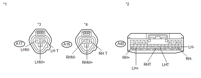
*1 |
Front view of wire harness connector (to Headlight Leveling Motor (Headlight Unit)) |
*3 |
LH Side |
|
*2 |
Front view of wire harness connector (to Headlight Leveling ECU Assembly) |
*4 |
RH Side |
| NG | |
REPAIR OR REPLACE HARNESS OR CONNECTOR |
|
|
3. |
REPLACE HEADLIGHT LEVELING MOTOR (HEADLIGHT UNIT) |
(a) Temporarily replace the headlight leveling motor with a new or normally functioning
one (See page .gif) ).
).
(b) Perform the Active Test of the leveling motors.
OK:
Headlight leveling motors operate normally.
| OK | |
PROCEED TO NEXT SUSPECTED AREA SHOWN IN PROBLEM SYMPTOMS TABLE |
| NG | |
REPLACE HEADLIGHT LEVELING ECU ASSEMBLY |
 Taillight Relay Circuit
DESCRIPTION
The main body ECU (driver side junction block assembly) controls the operation
of the TAIL relay.
WIRING DIAGRAM
CAUTION / NOTICE / HINT
NOTICE:
Inspect the fuses for circuits rel ...
 Headlight Leveling ECU Power Source Circuit
DESCRIPTION
This circuit detects the state of the ignition switch, and sends it to the headlight
leveling ECU assembly.
WIRING DIAGRAM
CAUTION / NOTICE / HINT
NOTICE:
Inspect the fuses for ci ...
Other materials about Toyota Venza:
Problem Symptoms Table
PROBLEM SYMPTOMS TABLE
HINT:
Use the table below to help determine the cause of problem symptoms.
If multiple suspected areas are listed, the potential causes of the symptoms
are listed in order of probability in the "Suspected Area" ...
Disassembly
DISASSEMBLY
PROCEDURE
1. REMOVE FUEL SENDER GAUGE
2. SEPARATE FUEL SUCTION PLATE SUB-ASSEMBLY
(a) Disconnect the fuel pump connector from the fuel suction plate.
NOTICE:
Do not damage the wire harness.
...
Data List / Active Test
DATA LIST / ACTIVE TEST
1. DATA LIST
HINT:
Using the Techstream to read the Data List allows the values or states of switches,
sensors, actuators and other items to be read without removing any parts. This non-intrusive
inspection can be very useful bec ...

0.1532