Toyota Venza: Windshield Deicer does not Operate
DESCRIPTION
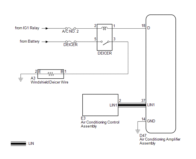
When the rear window defogger switch on the air conditioning control assembly is pressed, the operation signal is transmitted to the air conditioning amplifier assembly through the LIN communication line. When the air conditioning amplifier assembly receives the signal, it turns on the DEICER relay to operate the windshield deicer.
WIRING DIAGRAM
CAUTION / NOTICE / HINT
NOTICE:
Inspect the fuses for circuits related to this system before performing the following inspection procedure.
PROCEDURE
|
1. |
CHECK WINDOW DEFOGGER SYSTEM |
(a) Turn the ignition switch to ON, press the rear window defogger switch, and
check that the window defogger operates (See page
.gif) ).
).
OK:
The window defogger system operates normally.
| NG | .gif) |
GO TO WINDOW DEFOGGER SYSTEM |
|
.gif)
|
2. |
INSPECT DEICER RELAY |
|
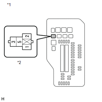
(a) Remove the DEICER relay from the engine room relay block. |
|
.png)
(b) Measure the resistance according to the value(s) in the table below.
Standard Resistance:
|
Tester Connection |
Condition |
Specified Condition |
|---|---|---|
|
3 - 5 |
Battery voltage applied between terminals 1 and 2 |
Below 1 Ω |
|
3 - 5 |
Battery voltage not applied between terminals 1 and 2 |
10 kΩ or higher |
| NG | |
REPLACE DEICER RELAY |
|
|
3. |
CHECK HARNESS AND CONNECTOR (DEICER RELAY POWER SOURCE) |
|
(a) Measure the voltage according to the value(s) in the table below. Standard Voltage:
|
|
| NG | |
REPAIR OR REPLACE HARNESS OR CONNECTOR |
|
|
4. |
CHECK HARNESS AND CONNECTOR (DEICER RELAY - AIR CONDITIONING AMPLIFIER ASSEMBLY) |
|
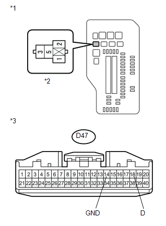
(a) Disconnect the D47 air conditioning amplifier assembly connector. |
|
(b) Measure the resistance according to the value(s) in the table below.
Standard Resistance:
|
Tester Connection |
Condition |
Specified Condition |
|---|---|---|
|
Engine room relay block DEICER relay terminal 1 - D47-18 (D) |
Always |
Below 1 Ω |
|
D47-14 (GND) - Body ground |
Always |
Below 1 Ω |
|
D47-18 (D) - Body ground |
Always |
10 kΩ or higher |
|
*1 |
Engine Room Relay Block |
|
*2 |
DEICER Relay Terminal |
|
*3 |
Front view of wire harness connector (to Air Conditioning Amplifier Assembly) |
| NG | |
REPAIR OR REPLACE HARNESS OR CONNECTOR |
|
|
5. |
CHECK HARNESS AND CONNECTOR (DEICER RELAY POWER SOURCE) |
|
(a) Measure the voltage according to the value(s) in the table below. Standard Voltage:
|
|
| NG | |
REPAIR OR REPLACE HARNESS OR CONNECTOR |
|
|
6. |
CHECK HARNESS AND CONNECTOR (DEICER RELAY - WINDSHIELD DEICER WIRE) |
|
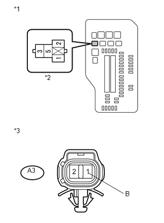
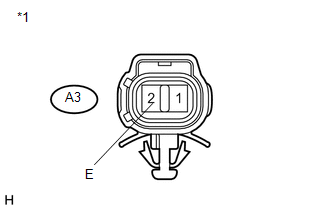
(a) Disconnect the A3 windshield deicer wire connector. |
|
(b) Measure the resistance according to the value(s) in the table below.
Standard Resistance:
|
Tester Connection |
Condition |
Specified Condition |
|---|---|---|
|
A3-1 (B) - engine room relay block DEICER relay terminal 3 |
Always |
Below 1 Ω |
|
A3-1 (B) - Body ground |
Always |
10 kΩ or higher |
|
Engine room relay block DEICER relay terminal 3 - Body ground |
Always |
10 kΩ or higher |
|
*1 |
Engine Room Relay Block |
|
*2 |
DEICER Relay Terminal |
|
*3 |
Front view of wire harness connector (to Windshield Deicer Wire) |
| NG | |
REPAIR OR REPLACE HARNESS OR CONNECTOR |
|
|
7. |
CHECK HARNESS AND CONNECTOR (WINDSHIELD DEICER WIRE - BODY GROUND) |
|
(a) Measure the resistance according to the value(s) in the table below. Standard Resistance:
|
|
| OK | |
REPLACE WINDSHIELD GLASS (WINDSHIELD DEICER WIRE) |
| NG | |
REPAIR OR REPLACE HARNESS OR CONNECTOR |
 Terminals Of Ecu
TERMINALS OF ECU
1. CHECK AIR CONDITIONING AMPLIFIER ASSEMBLY
(a) Disconnect the D47 air conditioning amplifier assembly connector.
(b) Measure the voltage and resistance according to the value(s ...
 Windshield Glass
...
Other materials about Toyota Venza:
Diagnostic Trouble Code Chart
DIAGNOSTIC TROUBLE CODE CHART
Navigation System
DTC Code
Detection Item
See page
B1532
LVDS Signal Malfunction (from Extension Module)
B1551
HD Radio Tuner ...
Unlock Warning Switch Circuit
DESCRIPTION
The key unlock warning switch assembly turns on when the ignition key is inserted
into the ignition key cylinder and turns off when the ignition key is removed.
The main body ECU (driver side junction block assembly) operates the key confinemen ...
Installation
INSTALLATION
PROCEDURE
1. INSTALL WINDSHIELD WIPER MOTOR ASSEMBLY
(a) Using a T30 "TORX" socket wrench, install the windshield wiper motor
assembly with the 2 bolts.
Torque:
7.5 N·m {76 kgf·cm, 66 in·lbf}
...

0.1495