Toyota Venza: Taillight Relay Circuit
DESCRIPTION
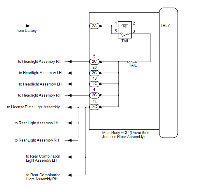
The main body ECU (driver side junction block assembly) controls the operation of the TAIL relay.
WIRING DIAGRAM
CAUTION / NOTICE / HINT
NOTICE:
Inspect the fuses for circuits related to this system before performing the following inspection procedure.
PROCEDURE
|
1. |
PERFORM ACTIVE TEST USING TECHSTREAM |
(a) Connect the Techstream to the DLC3.
(b) Turn the ignition switch to ON.
(c) Turn the Techstream on.
(d) Enter the following menus: Body Electrical / Main Body / Active Test.
(e) Check that the relay operates.
Main Body|
Tester Display |
Test Part |
Control Range |
Diagnostic Note |
|---|---|---|---|
|
Taillight Relay |
Taillight relay |
ON/OFF |
- |
OK:
Taillight relay operates. (Taillights illuminate.)
| OK | .gif) |
PROCEED TO NEXT SUSPECTED AREA SHOWN IN PROBLEM SYMPTOMS TABLE |
|
.gif)
|
2. |
INSPECT TAILLIGHT RELAY (TAIL) |
|
(a) Remove the taillight relay from the main body ECU (driver side junction block assembly). |
|
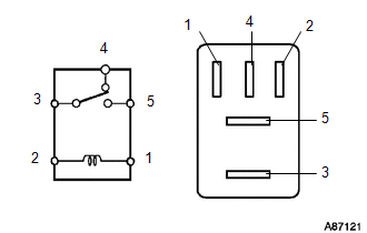
(b) Measure the resistance according to the value(s) in the table below.
Standard Resistance:
|
Tester Connection |
Condition |
Specified Condition |
|---|---|---|
|
3 - 5 |
Voltage is not applied between terminals 1 and 2 |
10 kΩ or higher |
|
Apply the battery voltage between terminals 1 and 2 |
Below 1 Ω |
|
|
3 - 4 |
Voltage is not applied between terminals 1 and 2 |
Below 1 Ω |
|
Apply the battery voltage between terminals 1 and 2 |
10 kΩ or higher |
| NG | |
REPLACE TAILLIGHT RELAY |
|
|
3. |
CHECK HARNESS AND CONNECTOR (BATTERY - MAIN BODY ECU (DRIVER SIDE JUNCTION BLOCK ASSEMBLY) |
|
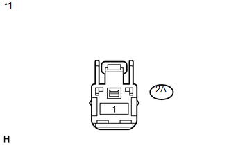
(a) Disconnect the 2A main body ECU (driver side junction block assembly) connector. |
|
(b) Measure the voltage according to the value(s) in the table below.
Standard Voltage:
|
Tester Connection |
Condition |
Specified Condition |
|---|---|---|
|
2A-1 - Body ground |
Always |
11 to 14 V |
|
*1 |
Front view of wire harness connector (to Main Body ECU (Driver Side Junction Block Assembly)) |
| OK | |
REPLACE MAIN BODY ECU (DRIVER SIDE JUNCTION BLOCK ASSEMBLY) |
| NG | |
REPAIR OR REPLACE HARNESS OR CONNECTOR |
 Parking Brake Switch Circuit
DESCRIPTION
The main body ECU (driver side junction block assembly) detects the condition
of the parking brake switch.
WIRING DIAGRAM
PROCEDURE
1.
READ VALUE USING TECHS ...
 Headlight Beam Level Control Actuator Circuit
DESCRIPTION
The headlight leveling ECU assembly actuates the headlight leveling motor according
to vehicle conditions.
WIRING DIAGRAM
PROCEDURE
1.
READ VALUE USING TECHS ...
Other materials about Toyota Venza:
Throttle / Pedal Position Sensor / Switch "A" Circuit Malfunction (P0120-P0123,P0220,P0222,P0223,P2135)
DESCRIPTION
HINT:
These DTCs relate to the throttle position sensor.
The throttle position sensor is mounted on the throttle body, and detects the
opening angle of the throttle valve. This sensor is a non-contact type sensor. It
uses hall-effect element ...
Occupant Classification Ecu
Components
COMPONENTS
ILLUSTRATION
ILLUSTRATION
On-vehicle Inspection
ON-VEHICLE INSPECTION
CAUTION / NOTICE / HINT
CAUTION:
Be sure to follow the correct removal and installation procedures of the occupant
classification ECU.
PROCEDURE
1. ...
Interior Light Circuit
DESCRIPTION
The illuminated entry system controls the roof console box assembly, step or
spot light assembly and transponder key amplifier*1.
HINT:
*1: w/o Smart Key System
WIRING DIAGRAM
PROCEDURE
1.
PERFORM ACTIVE TEST USING ...

0.1558