Toyota Venza: Gauges and meters
►Vehicles with smart key system The following gauges, meters and display illuminate when the “ENGINE START STOP” switch is in IGNITION ON mode.
►Vehicles without smart key system The following gauges, meters and displays illuminate when the engine switch is in the “ON” position.
1. Tachometer
Displays the engine speed in revolutions per minute.
2. Speedometer
Displays the vehicle speed.
3. Fuel gauge
Displays the quantity of fuel remaining in the tank.
4. Engine coolant temperature gauge Displays the engine coolant temperature.
5. Odometer/trip meter and trip meter reset button Switches between odometer and trip meter displays. Pushing and holding the button will reset the trip meter when the trip meter is being displayed.
6. Odometer and trip meter Odometer: Displays the total distance the vehicle has been driven.
Trip meter: Displays the distance the vehicle has been driven since the meter was last reset. Trip meters A and B can be used to record and display different distances independently.
Instrument panel light control
The brightness of the instrument panel lights can be adjusted.
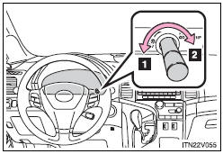
1. Darker
2. Brighter
NOTICE
- To prevent damage to the engine and its components
• Do not let the indicator needle of the tachometer enter the red zone, which indicates the maximum engine speed.
• The engine may be overheating if the engine coolant temperature gauge is in the red zone (“H”). In this case, immediately stop the vehicle in a safe place, and check the engine after it has cooled completely.

 Indicators and warning lights
The indicator and warning lights on the instrument cluster and center panel
inform the driver of the status of the vehicle’s various systems.
For the purpose of explanation, the following illustr ...
Other materials about Toyota Venza:
Transmission Wire(when Not Using The Engine Support Bridge)
Components
COMPONENTS
ILLUSTRATION
Installation
INSTALLATION
PROCEDURE
1. INSTALL TRANSMISSION WIRE
(a) Coat the O-ring with ATF.
(b) Coat the bolt with ATF.
(c) Install the tr ...
System Diagram
SYSTEM DIAGRAM
1. AUTOMATIC LIGHT CONTROL SYSTEM
2. LIGHT AUTO TURN-OFF SYSTEM
Communication Table
Transmitter
Receiver
Line
Data Name
Certification ECU (Smart Key ECU Assembly)
Mai ...
System Description
SYSTEM DESCRIPTION
1. DESCRIPTION
The power steering system generates torque through the operation of
the motor and the reduction gear installed on the column shaft in order
to assist steering effort.
The power steering ECU determines dire ...

0.1176