Toyota Venza: Floor mats
Use only floor mats designed specifically for vehicles of the same model and model year as your vehicle. Fix them securely in place onto the carpet.
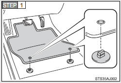
Insert the retaining hooks (clips) into the floor mat eyelets.
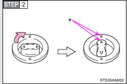
Turn the upper knob of each retaining hook (clip) to secure the floor mats in place.
*: Always align the  marks.
The shape of the retaining hooks (clips) may differ from that shown in the illustration.
CAUTION
Observe the following precautions.
Failure to do so may cause the driver’s floor mat to slip, possibly interfering with the pedals while driving. An unexpectedly high speed may result or it may become difficult to stop the vehicle, leading to a serious accident.
- When installing the driver’s floor mat
• Do not use floor mats designed for other models or different model year vehicles, even if they are Toyota Genuine floor mats.
• Only use floor mats designed for the driver’s seat.
• Always install the floor mat securely using the retaining hooks (clips) provided.
• Do not use two or more floor mats on top of each other.
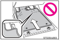
• Do not place the floor mat bottom-side up or upside-down.
- Before driving
• Check that the floor mat is securely fixed in the correct place with all the provided retaining hooks (clips). Be especially careful to perform this check after cleaning the floor.
• With the engine stopped and the shift lever in P, fully depress each pedal to the floor to make sure it does not interfere with the floor mat.
 Assist grips (folding type)
An assist grip installed on the ceiling can be used to support your body while
sitting on the seat.
CAUTION
- Assist grip
Do not use the assist grip when getting in or out of the vehicle ...
 Luggage compartment features
- Cargo hooks
Cargo hooks are provided for securing loose items.
- Shopping bag hooks
- Auxiliary box
Lift the right side deck board.
- Luggage cover
Pull out the ...
Other materials about Toyota Venza:
Engine
General Maintenance
GENERAL MAINTENANCE
CAUTION / NOTICE / HINT
HINT:
Perform these procedures after the engine has cooled down.
PROCEDURE
1. INSPECT DRIVE BELT
Engine Type
See Procedure
2GR-FE
See pag ...
Satellite Radio Broadcast cannot be Selected or After Selecting Broadcast, Broadcast
cannot be Added into Memory
CAUTION / NOTICE / HINT
NOTICE:
Some satellite radio broadcasts require payment. A contract must be made between
a satellite radio company and the user. If the contract expires, it will not be
possible to listen to the broadcast.
PROCEDURE
1 ...
Front Airbag Sensor RH Malfunction (B1610/13)
DESCRIPTION
The front airbag sensor RH circuit consists of the center airbag sensor assembly
and front airbag sensor RH.
The front airbag sensor RH detects impacts to the vehicle and sends signals to
the center airbag sensor assembly to determine if the ...

0.1305