Toyota Venza: Engine Switch Illumination Circuit
DESCRIPTION
The illuminated entry system controls the engine switch illumination.
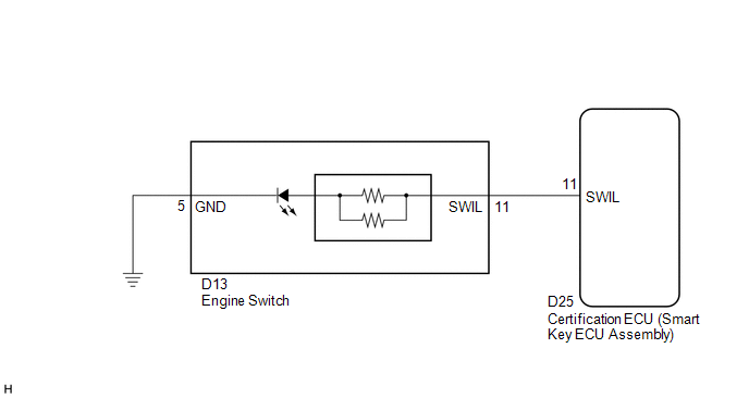
WIRING DIAGRAM
PROCEDURE
|
1. |
PERFORM ACTIVE TEST USING TECHSTREAM |
(a) Connect the Techstream to the DLC3.
(b) Turn the ignition switch to ON.
(c) Turn the Techstream on.
(d) Enter the following menus: Body Electrical / Smart Key / Active Test.
(e) Check that the illumination operates.
Smart Key|
Tester Display |
Test Part |
Control Range |
Diagnostic Note |
|---|---|---|---|
|
Power/Engine SW Light |
Engine switch illumination |
ON/OFF |
- |
OK:
Engine switch illumination comes on.
| OK | .gif) |
PROCEED TO NEXT SUSPECTED AREA SHOWN IN PROBLEM SYMPTOMS TABLE |
|
.gif)
|
2. |
INSPECT ENGINE SWITCH |
(a) Remove the engine switch (See page .gif) ).
).
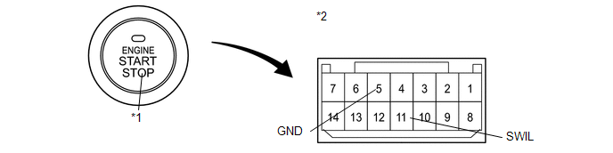
(b) Apply battery voltage to the engine switch.
(c) Check that the illumination comes on.
OK:
|
Measurement Condition |
Specified Condition |
|---|---|
|
Battery positive (+) → Terminal 11 (SWIL) Battery negative (-) → Terminal 5 (GND) |
Engine switch illumination comes on |
|
*1 |
Illumination |
*2 |
Component without harness connected (Engine Switch) |
| NG | |
REPLACE ENGINE SWITCH |
|
|
3. |
CHECK HARNESS AND CONNECTOR (ENGINE SWITCH - CERTIFICATION ECU AND BODY GROUND) |
|
(a) Disconnect the D25 certification ECU (smart Key ECU Assembly) connector. |
|
(b) Disconnect the D13 engine switch connector.
(c) Measure the resistance according to the value(s) in the table below.
Standard Resistance:
|
Tester Connection |
Condition |
Specified Condition |
|---|---|---|
|
D13-11 (SWIL) - D25-11 (SWIL) |
Always |
Below 1 Ω |
|
D13-5 (GND) - Body ground |
Always |
Below 1 Ω |
|
D13-11 (SWIL) - Body ground |
Always |
10 kΩ or higher |
|
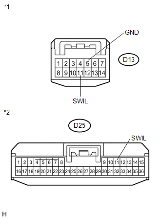
*1 |
Front view of wire harness connector (to Engine Switch) |
|
*2 |
Front view of wire harness connector (to Certification ECU (Smart Key ECU Assembly)) |
| OK | |
REPLACE CERTIFICATION ECU (SMART KEY ECU ASSEMBLY) |
| NG | |
REPAIR OR REPLACE HARNESS OR CONNECTOR |
 Interior Light Auto Cut Circuit
DESCRIPTION
When battery saving control operates while the interior lights are on, the main
body ECU (driver side junction block assembly) opens the DOME CUT relay to turn
off the lights.
WIRING ...
 Interior Light Power Source Circuit
DESCRIPTION
The main body ECU (driver side junction block assembly) controls operation of
the DOME CUT relay in order to supply power to the interior lights.
WIRING DIAGRAM
CAUTION / NOTICE / H ...
Other materials about Toyota Venza:
Components
COMPONENTS
ILLUSTRATION
ILLUSTRATION
ILLUSTRATION
ILLUSTRATION
ILLUSTRATION
...
Disassembly
DISASSEMBLY
CAUTION / NOTICE / HINT
NOTICE:
When using a vise, do not overtighten it.
PROCEDURE
1. REMOVE STEERING LOCK ACTUATOR ASSEMBLY (w/ Smart Key System)
(a) Secure the steering column assembly in a vise.
(b) Using a center punch, mark the center ...
Power Mirrors do not Return to Memorized Position
SYSTEM DESCRIPTION
If either the M1 or M2 seat memory switch is pressed, the outer mirror control
ECU assembly (driver door) detects the seat memory switch status and sends the switch
signal to the main body ECU (driver side junction block assembly) via C ...

0.1769