Toyota Venza: Indicator Circuit
DESCRIPTION
The headlight beam level control system indicator light in the combination meter assembly comes on for approximately 3 seconds when the ignition switch is turned to ON. The indicator light also comes on when the headlight leveling ECU assembly detects a malfunction.
WIRING DIAGRAM
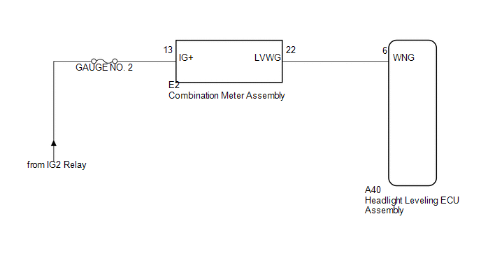
PROCEDURE
|
1. |
CHECK HARNESS AND CONNECTOR (BATTERY - COMBINATION METER ASSEMBLY) |
|
(a) Disconnect the E2 combination meter assembly connector. |
|
(b) Measure the voltage according to the value(s) in the table below.
Standard Voltage:
|
Tester Connection |
Switch Condition |
Specified Condition |
|---|---|---|
|
E2-13 (IG+) - Body ground |
Ignition switch ON |
11 to 14 V |
|
Ignition switch off |
Below 1 V |
|
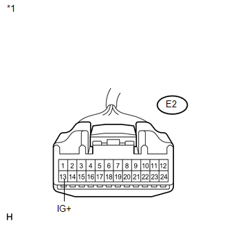
*1 |
Front view of wire harness connector (to Combination Meter Assembly) |
| NG | .gif) |
REPAIR OR REPLACE HARNESS OR CONNECTOR |
|
.gif)
|
2. |
CHECK HARNESS AND CONNECTOR (COMBINATION METER ASSEMBLY - HEADLIGHT LEVELING ECU ASSEMBLY) |
|
(a) Disconnect the A40 headlight leveling ECU assembly connector. |
|
(b) Measure the resistance according to the value(s) in the table below.
Standard Resistance:
|
Tester Connection |
Condition |
Specified Condition |
|---|---|---|
|
A40-6 (WNG) - E2-22 (LVWG) |
Always |
Below 1 Ω |
|
A40-6 (WNG) - Body ground |
Always |
10 kΩ or higher |
|
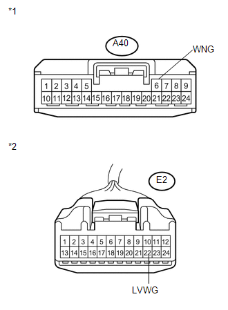
*1 |
Front view of wire harness connector (to Headlight Leveling ECU Assembly) |
|
*2 |
Front view of wire harness connector (to Combination Meter Assembly) |
| NG | |
REPAIR OR REPLACE HARNESS OR CONNECTOR |
|
|
3. |
INSPECT COMBINATION METER ASSEMBLY |
|
(a) Reconnect the E2 combination meter assembly connector. |
|
(b) Measure the voltage according to the value(s) in the table below.
Standard Voltage:
|
Tester Connection |
Switch Condition |
Specified Condition |
|---|---|---|
|
E2-22 (LVWG) - Body ground |
Ignition switch ON |
11 to 14 V |
|
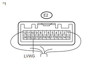
*1 |
Component with harness connected (Combination Meter Assembly) |
| OK | |
PROCEED TO NEXT SUSPECTED AREA SHOWN IN PROBLEM SYMPTOMS TABLE |
| NG | |
REPLACE COMBINATION METER ASSEMBLY |
 Headlight Leveling ECU Power Source Circuit
DESCRIPTION
This circuit detects the state of the ignition switch, and sends it to the headlight
leveling ECU assembly.
WIRING DIAGRAM
CAUTION / NOTICE / HINT
NOTICE:
Inspect the fuses for ci ...
 Speed Signal Circuit
DESCRIPTION
The headlight leveling ECU assembly receives the vehicle speed signal from the
combination meter assembly.
HINT:
A voltage of 12 V or 5 V is output from each ECU and then inpu ...
Other materials about Toyota Venza:
Throttle Actuator Control System - Stuck Open (P2111,P2112)
DESCRIPTION
The throttle actuator is operated by the ECM, and opens and closes the throttle
valve using gears. The opening angle of the throttle valve is detected by the throttle
position sensor, which is mounted on the throttle body. The throttle positio ...
Dtc Check / Clear
DTC CHECK / CLEAR
1. CHECK DTC
(a) Connect the Techstream to the DLC3.
(b) Turn the ignition switch to ON.
(c) Turn the Techstream on.
(d) Read the DTCs by following the directions on the Techstream screen.
HINT:
Refer to the Techstream operator's m ...
Inspection
INSPECTION
PROCEDURE
1. INSPECT TIE ROD ASSEMBLY LH
(a) Secure the tie rod assembly LH in a vise.
(b) Install the nut to the stud bolt.
(c) Flip the ball joint back and forth 5 times.
(d) Set a to ...

0.1733