Toyota Venza: Interior Light Power Source Circuit
DESCRIPTION
The main body ECU (driver side junction block assembly) controls operation of the DOME CUT relay in order to supply power to the interior lights.
WIRING DIAGRAM
.png)
CAUTION / NOTICE / HINT
NOTICE:
Inspect the fuses for circuits related to this system before performing the following inspection procedure.
PROCEDURE
|
1. |
INSPECT DOME CUT RELAY |
(a) Remove the DOME CUT relay.
|
(b) Measure the resistance according to the value(s) in the table below. Standard Resistance:
|
|
.png)
| NG | .gif) |
REPLACE DOME CUT RELAY |
|
.gif)
|
2. |
CHECK HARNESS AND CONNECTOR (BATTERY - MAIN BODY ECU (DRIVER SIDE JUNCTION BLOCK ASSEMBLY)) |
(a) Disconnect the 2C main body ECU (driver side junction block assembly) connector.
(b) Measure the voltage according to the value(s) in the table below.
Standard Voltage:
|
Tester Connection |
Condition |
Specified Condition |
|---|---|---|
|
2C-27 - Body ground |
Ignition switch off |
11 to 14 V |
| NG | |
REPAIR OR REPLACE HARNESS OR CONNECTOR |
|
|
3. |
CHECK HARNESS AND CONNECTOR (DOME CUT RELAY - MAIN BODY ECU (DRIVER SIDE JUNCTION BLOCK ASSEMBLY) AND BODY GROUND) |
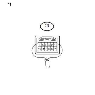
(a) Disconnect the 2R main body ECU (driver side junction block assembly) connector.
(b) Measure the resistance according to the value(s) in the table below.
Standard Resistance:
|
Tester Connection |
Condition |
Specified Condition |
|---|---|---|
|
Relay Terminal 5 - 2R-6 |
Always |
Below 1 Ω |
|
Relay Terminal 2 - 2R-7 |
Always |
Below 1 Ω |
|
Relay Terminal 5 - Body ground |
Always |
10 kΩ or higher |
|
Relay Terminal 2 - Body ground |
Always |
10 kΩ or higher |
|
Relay Terminal 1 - Body ground |
Always |
Below 1 Ω |
| NG | |
REPAIR OR REPLACE HARNESS OR CONNECTOR |
|
|
4. |
INSPECT MAIN BODY ECU (DRIVER SIDE JUNCTION BLOCK ASSEMBLY) |
(a) Install the DOME CUT relay.
(b) Reconnect the 2C main body ECU (driver side junction block assembly) connector.
|
(c) Reconnect the 2R main body ECU (driver side junction block assembly) connector. |
|
(d) Measure the voltage according to the value(s) in the table below.
Standard Voltage:
|
Tester Connection |
Condition |
Specified Condition |
|---|---|---|
|
2R-6 - Body ground |
Ignition switch off |
11 to 14 V |
|
2R-7 - Body ground |
Ignition switch ON |
11 to 14 V |
|
*1 |
Component with harness connected (Main Body ECU (Driver Side Junction Block Assembly)) |
| OK | |
REPAIR OR REPLACE HARNESS OR CONNECTOR (DOME CUT RELAY - EACH LIGHT) |
| NG | |
PROCEED TO NEXT SUSPECTED AREA SHOWN IN PROBLEM SYMPTOMS TABLE |
 Engine Switch Illumination Circuit
DESCRIPTION
The illuminated entry system controls the engine switch illumination.
WIRING DIAGRAM
PROCEDURE
1.
PERFORM ACTIVE TEST USING TECHSTREAM
(a) Connect th ...
 Door Unlock Detection Switch Circuit
DESCRIPTION
The main body ECU (driver side junction block assembly) detects the condition
of the door unlock detection switch.
WIRING DIAGRAM
PROCEDURE
1.
READ VALUE USI ...
Other materials about Toyota Venza:
Rear Airbag Sensor LH Circuit Malfunction (B1635/24)
DESCRIPTION
The side collision sensor LH circuit (to determine deployment of the front seat
side airbag assembly LH and curtain shield airbag assembly LH) is composed of the
center airbag sensor assembly, rear airbag sensor LH and side airbag sensor LH.
...
Cellular Phone Registration Failure
PROCEDURE
1.
CHECK USAGE CONDITION
(a) Check that the vehicle and cellular phone meet the following conditions:
NOTICE:
If changing cellular phone settings, updating software, etc. is necessary, make
sure to obtain the per ...
Brake Line
Precaution
PRECAUTION
1. TROUBLESHOOTING PRECAUTION
NOTICE:
Since the brake lines are critical safety related parts, be sure to
disassemble and inspect the components if a brake fluid leak is found. If
any abnormality is found, replace th ...

0.1289