Toyota Venza: Door Control Switch
Components
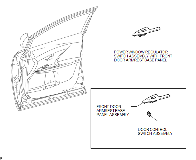
COMPONENTS
ILLUSTRATION
Inspection
INSPECTION
PROCEDURE
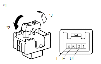
1. INSPECT DOOR CONTROL SWITCH ASSEMBLY
|
(a) Measure the resistance according to the value(s) in the table below. Standard Resistance:
If the result is not as specified, replace the door control switch assembly |
|
Removal
REMOVAL
PROCEDURE
1. REMOVE POWER WINDOW REGULATOR SWITCH ASSEMBLY WITH FRONT DOOR ARMREST BASE PANEL
.gif)
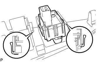
2. REMOVE DOOR CONTROL SWITCH ASSEMBLY
|
(a) Disengage the 2 claws and remove the door control switch assembly. |
|
Installation
INSTALLATION
PROCEDURE
1. INSTALL DOOR CONTROL SWITCH ASSEMBLY
|
(a) Engage the 2 claws and install the door control switch assembly. |
|
.png)
2. INSTALL POWER WINDOW REGULATOR SWITCH ASSEMBLY WITH FRONT DOOR ARMREST BASE PANEL
.gif)
 Installation
INSTALLATION
PROCEDURE
1. INSTALL DOOR CONTROL RECEIVER
(a) Install the door control receiver with the bolt.
(b) Connect the connector.
2 ...
 Door Control Transmitter(w/ Smart Key System)
Components
COMPONENTS
ILLUSTRATION
Removal
REMOVAL
PROCEDURE
1. REMOVE TRANSMITTER BATTERY
Inspection
INSPECTION
PROCEDURE
1. INSPECT DOOR CONTROL TRANSMITTER
(a) Inspect operati ...
Other materials about Toyota Venza:
Installation
INSTALLATION
CAUTION / NOTICE / HINT
NOTICE:
Always use a new grommet and valve core when installing the tire pressure
warning valve and transmitter.
Check that the washer and nut are not damaged, and replace them if necessary.
Write ...
On-vehicle Inspection
ON-VEHICLE INSPECTION
PROCEDURE
1. INSPECT DISCHARGE HEADLIGHT BULB
NOTICE:
Confirm the following items before replacing a discharge headlight bulb. If a
malfunction is discovered and repaired, perform the inspection again to confirm
the repair.
...
Power Back Door Touch Sensor
Components
COMPONENTS
ILLUSTRATION
Removal
REMOVAL
PROCEDURE
1. REMOVE UPPER BACK WINDOW PANEL TRIM
2. REMOVE BACK DOOR PANEL TRIM ASSEMBLY
3. DISCONNECT POWER BACK DOOR ROD (for LH Side)
4. REMOVE BACK DOOR TRIM COVER
5. REMOVE POW ...

0.1411