Toyota Venza: ECM Communication Stop Mode
DESCRIPTION
|
Detection Item |
Symptom |
Trouble Area |
|---|---|---|
|
ECM Communication Stop Mode |
|
|
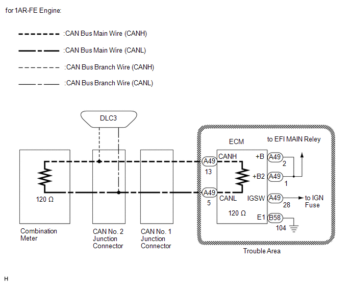
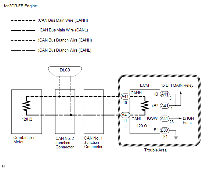
WIRING DIAGRAM
CAUTION / NOTICE / HINT
NOTICE:
- Turn the ignition switch off before measuring the resistances between CAN bus main wires and between CAN bus branch wires.
- Turn the ignition switch off before inspecting CAN bus wires for a ground short.
- After the ignition switch is turned off, check that the key reminder warning system and light reminder warning system are not operating.
- Before measuring the resistance, leave the vehicle as is for at least 1 minute and do not operate the ignition switch, any other switches or the doors. If any doors need to be opened in order to check connectors, open the doors and leave them open.
HINT:
- Operating the ignition switch, any other switches or a door triggers related ECU and sensor communication on the CAN. This communication will cause the resistance value to change.
- Even after DTCs are cleared, if a DTC is stored again after driving the vehicle for a while, the malfunction may be occurring due to vibration of the vehicle. In such a case, wiggling the ECUs or wire harness while performing the inspection below may help determine the cause of the malfunction.
PROCEDURE
|
1. |
CHECK CAN BUS WIRE FOR DISCONNECTION (ECM MAIN WIRE) |
(a) Turn the ignition switch off.
(b) for 1AR-FE engine:
|
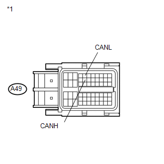
(1) Disconnect the connector of the ECM. Text in Illustration
|
|
(2) Measure the resistance according to the value(s) in the table below.
Standard Resistance:
|
Tester Connection |
Switch Condition |
Specified Condition |
|---|---|---|
|
A49-13 (CANH) - A49-5 (CANL) |
Ignition switch off |
108 to 132 Ω |
(c) for 2GR-FE engine:
|
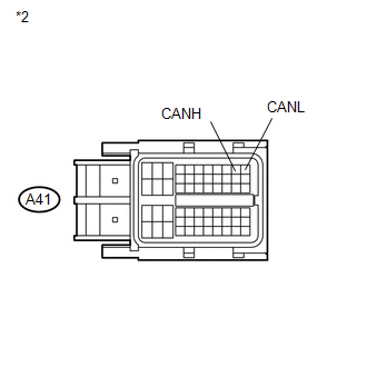
(1) Disconnect the connector of the ECM. Text in Illustration
|
|
(2) Measure the resistance according to the value(s) in the table below.
Standard Resistance:
|
Tester Connection |
Switch Condition |
Specified Condition |
|---|---|---|
|
A41-10 (CANH) - A41-11 (CANL) |
Ignition switch off |
108 to 132 Ω |
| NG | .gif) |
REPAIR OR REPLACE CAN BUS MAIN WIRE OR CONNECTOR (ECM MAIN WIRE) |
|
.gif)
|
2. |
CHECK HARNESS AND CONNECTOR (POWER SOURCE TERMINAL) |
(a) Check for ECM Power Source Circuit (1AR-FE: See page
.gif) , 2GR-FE: See page
).
, 2GR-FE: See page
).
|
Result |
Proceed to |
|---|---|
|
OK (for 1AR-FE engine) |
A |
|
OK (for 2GR-FE engine) |
B |
|
NG |
C |
| A | |
REPLACE ECM |
| B | |
REPLACE ECM |
| C | |
REPAIR OR REPLACE HARNESS OR CONNECTOR (POWER SOURCE CIRCUIT) |
 Yaw Rate Sensor Communication Stop Mode
DESCRIPTION
Detection Item
Symptom
Trouble Area
Yaw Rate Sensor Communication Stop Mode
"Yaw Rate/Decelerate Sensor" ...
 Main Body ECU Communication Stop Mode
DESCRIPTION
Detection Item
Symptom
Trouble Area
Main Body ECU Communication Stop Mode
"Main Body" is not displayed on ...
Other materials about Toyota Venza:
Installation
INSTALLATION
PROCEDURE
1. INSTALL INSTRUMENT PANEL STAY
(a) Engage the 3 claws to install the 3 instrument panel stays.
2. INSTALL INSTRUMENT PANEL CLIP
(a) Engage the 2 claws to install ...
Side Turn Signal Light Assembly
Components
COMPONENTS
ILLUSTRATION
Removal
REMOVAL
CAUTION / NOTICE / HINT
HINT:
Use the same procedure for the RH and LH sides.
The procedure described below is for the LH side.
PROCEDURE
1. REMOVE OUTER MIRROR
2. REMOVE O ...
Radio Broadcast cannot be Received or Poor Reception
PROCEDURE
1.
CHECK NAVIGATION RECEIVER ASSEMBLY
(a) Check the radio automatic station search function.
(1) Check the radio automatic station search function by activating it.
Result
Proceed to
...

0.1742