Toyota Venza: Disassembly
DISASSEMBLY
PROCEDURE
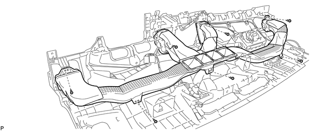
1. REMOVE NO. 1 SIDE DEFROSTER NOZZLE DUCT
|
(a) Remove the 2 screws <E> or <F> and remove the No. 1 side defroster nozzle duct. |
|
2. REMOVE NO. 2 SIDE DEFROSTER NOZZLE DUCT
|
(a) Remove the 2 screws <E> or <F> and remove the No. 2 side defroster nozzle duct. |
|
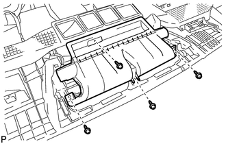
3. REMOVE DEFROSTER NOZZLE ASSEMBLY
|
(a) Remove the 4 screws <E> or <F> and remove the defroster nozzle assembly. |
|
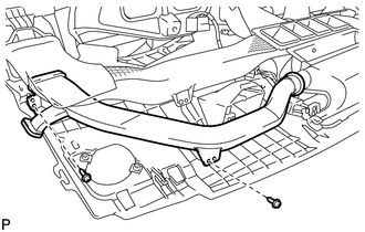
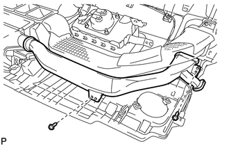
4. REMOVE HEATER TO REGISTER DUCT
(a) Remove the 7 screws <E> or <F> and remove the heater to register duct.
5. REMOVE NO. 1 ANTENNA CORD SUB-ASSEMBLY
.gif)
6. REMOVE NAVIGATION ANTENNA ASSEMBLY (w/ Navigation System)
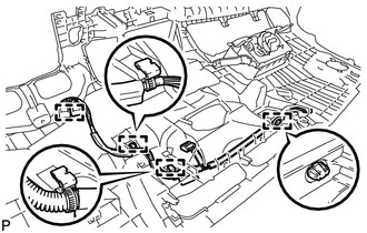
7. REMOVE NO. 3 INSTRUMENT PANEL WIRE
|
(a) Disengage the 4 clamps and remove the No. 3 instrument panel wire. |
|
8. REMOVE FRONT PASSENGER AIRBAG ASSEMBLY
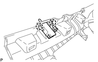
9. REMOVE GLOVE BOX LIGHT ASSEMBLY
|
(a) Disengage the 2 claws and remove the glove box light assembly. |
|
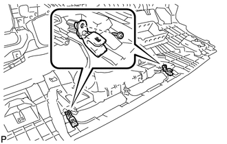
10. REMOVE NO. 1 INSTRUMENT PANEL PIN
|
(a) Remove the 2 screws <E> or <F> and the 2 No. 1 instrument panel pins. |
|
 Removal
REMOVAL
PROCEDURE
1. PRECAUTION
(See page )
2. ALIGN FRONT WHEELS FACING STRAIGHT AHEAD
3. DISCONNECT CABLE FROM NEGATIVE BATTERY TERMINAL
CAUTION:
Wait at least 90 seconds after disconnecting ...
 Reassembly
REASSEMBLY
PROCEDURE
1. INSTALL NO. 1 INSTRUMENT PANEL PIN
(a) Install the 2 No. 1 instrument panel pins with the 2 screws <E> or
<F>.
...
Other materials about Toyota Venza:
System Description
SYSTEM DESCRIPTION
1. SEAT BELT WARNING SYSTEM DESCRIPTION
If a seat belt is not fastened, this system flashes the seat belt warning light
or sounds the seat belt warning buzzer as a reminder.
(a) Driver side seat belt warning light:
When the driver side ...
Reassembly
REASSEMBLY
PROCEDURE
1. INSTALL NO. 1 INSTRUMENT PANEL PIN
(a) Install the 2 No. 1 instrument panel pins with the 2 screws <E> or
<F>.
2. INSTALL GLOVE BOX LIGHT ASSEMBLY
...
Motor Rotation Angle Sensor Malfunction (C1528)
DESCRIPTION
The motor rotation angle sensor detects the motor rotation angle and sends this
information to the power steering ECU.
DTC No.
DTC Detection Condition
Trouble Area
C1528
Motor rotatio ...

0.1681