Toyota Venza: Operation Check
OPERATION CHECK
1. AUTOMATIC LIGHT CONTROL SYSTEM OPERATION CHECK
(a) Turn the ignition switch to ON.
(b) Turn the light control switch to the AUTO position.
(c) Cover the automatic light control sensor.
(d) Check that the taillights and low beam headlights come on.
(e) Uncover the automatic light control sensor.
(f) Check that the low beam headlights and taillights go off.
2. LIGHT AUTO TURN-OFF SYSTEM OPERATION CHECK
(a) When only the taillights are on.
(1) Close the driver side door.
(2) Turn the ignition switch to ON.
(3) Turn the light control switch to the tail position.
(4) Turn the ignition switch off.
(5) Open the driver side door.
(6) Check that the taillights go off immediately.
(b) When low beam headlights are on.
(1) Close all of the doors.
(2) Turn the ignition switch to ON.
(3) Turn the low beam headlights, high beam headlights or front fog lights on.
(4) Turn the ignition switch off.
(5) Open any door.
(6) Close all of the doors.
(7) Check that all of lights go off after 30 seconds (delay function).
HINT:
If the lock button on the key is pushed after the doors are locked, all lights will go off immediately.
3. DAYTIME RUNNING LIGHT SYSTEM OPERATION CHECK
(a) Turn the light control switch off.
(b) Start the engine.
(c) Release the parking brake.
(d) Check that the daytime running lights come on.
4. HID HEADLIGHT SYSTEM OPERATION CHECK
(a) Perform the following diagnosis procedure when both of the following conditions are met: 1) the light control ECU is not visibly damaged, and 2) the light control ECU has been struck but is operating normally. If all of the following diagnosis results are normal, the light control ECU can be reused.
(1) Perform low beam headlight cold starts (10 minutes or more off, then turned on) and hot starts (15 minutes or more on, 1 minute off, then turned on again) several times. Check that the low beam headlights illuminate normally.
(2) For 5 minutes immediately after the lights are started cold (before the lights stabilize), monitor the light output and check that the lights do not flicker or show signs of instability.
(3) Install bulbs that have approximately the same usage time, and illuminate the low beam headlights for approximately 30 seconds. Check that the brightness of the left and right bulbs are approximately the same, and that the illumination is stable.
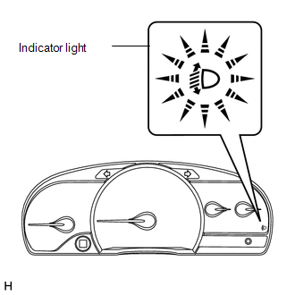
5. HEADLIGHT BEAM LEVEL CONTROL SYSTEM OPERATION CHECK
(a) Check that the initialization (determination of the initial position) of the headlight leveling motor (headlight unit) is performed when the ignition switch is turned to ON.
(b) Check that the headlight beam level control indicator light in the combination meter assembly comes on for approximately 3 seconds and then goes off when the ignition switch is turned to ON.
(c) Check that the projector moves when: the rear of the vehicle is moved up or down while the engine is running, vehicle is stopped, and the light control switch is in the head position.
NOTICE:
Change the vehicle height slowly.
6. AUTOMATIC HIGH BEAM SYSTEM OPERATION CHECK
(a) Check the operation of the inner rear view mirror assembly indicator light.
(1) Turn the ignition switch to ON.
(2) Check that the inner rear view mirror assembly indicator light comes on.
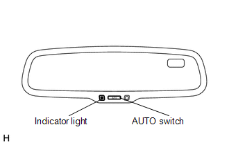
(3) Press the inner rear view mirror assembly AUTO switch once.
(4) Check that the inner rear view mirror assembly indicator light goes off.
(5) Press the inner rear view mirror assembly AUTO switch once again.
(6) Check that the inner rear view mirror assembly indicator light comes on.
HINT:
If the inner rear view mirror assembly indicator light flashes, turn the ignition switch off then turn the ignition switch to ON. If the inner rear view mirror assembly indicator light flashes continuously, replace the inner rear view mirror assembly.
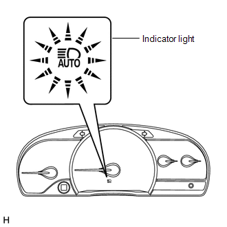
(b) Check the operation of the automatic high beam indicator light.
(1) Turn the ignition switch to ON.
(2) Move the shift lever to any position except R.
(3) Turn the light control switch to the AUTO position.
(4) Cover the automatic light control sensor to turn the low beam headlights on.
(5) Turn the dimmer switch to the high position.
(6) Check that the automatic high beam indicator comes on.
(c) Check the operation of the automatic high beam function.
(1) At night, when driving the vehicle with the automatic high beam system in standby mode, check that the high beams automatically turn on after a short delay when all of the following conditions are met:
- Vehicle speed is more than 20 mph (32 km/h).
- The area in front of the vehicle is dark.
- There are no oncoming vehicles with headlights on.
- There are no preceding vehicles with taillights on.
- There are few streetlights along the street ahead.
(2) At night, when driving the vehicle with the high beams turned on by the automatic high beam system, check that the automatic high beam system turns off the high beams and returns to standby mode when any of the following conditions are met:
- Vehicle speed is less than 20 mph (32 km/h).
- The level of ambient light is higher than a specified threshold.
- There are oncoming vehicles with headlights on.
- There are preceding vehicles with taillights on.
- Light from streetlights ahead is higher than a specified threshold.
(d) Using the following procedure, the automatic high beam operation can be checked without driving the vehicle.
(1) Connect terminals 4 (CG) and 8 (LVL) of the DLC3 using SST.
SST: 09843-18040
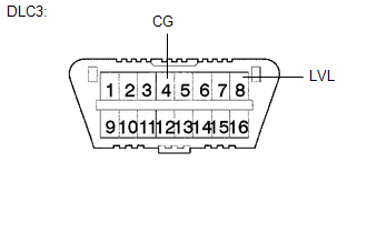
(2) Turn the ignition switch to ON.
(3) Disconnect SST within 10 seconds after turning the ignition switch to ON.
(4) After more than 1 second and less than 10 seconds, connect terminals 4 (CG) and 8 (LVL) of the DLC3 using SST again.
(5) Check that the inner rear view mirror assembly indicator light flashes.
(6) Check that the high beam headlights come on when the surrounding area is dark enough.
(7) Shine a flashlight, white LED or red LED on the camera built into the inner rear view mirror assembly.
(8) Check that the high beam headlights go off.
NOTICE:
The high beams may not turn on or may not change to low beams when the surrounding area is bright or due to other lighting conditions. Therefore, this function check should not be used as the only method of determining if a malfunction is present (if parts need to be replaced).
7. DOOR MIRROR FOOT LIGHT SYSTEM OPERATION CHECK
(a) The operation and condition of this control are described below.
|
Operation |
Condition |
|---|---|
|
Illuminate for 15 seconds, and then fade out |
When any of the following conditions is met, the lights illuminate for 15 seconds, and then fade out:
|
|
Fade out immediately |
When any of the following conditions is met, the lights fade out immediately:
|
HINT:
*1: When the lights are on, if the key leaves the actuation areas around the doors, after approximately 3 seconds, the door mirror foot lights fade out.
 How To Proceed With Troubleshooting
CAUTION / NOTICE / HINT
HINT:
Use the following procedure to troubleshoot the lighting system.
*: Use the Techstream.
PROCEDURE
1.
VEHICLE BROUGHT TO WO ...
 Customize Parameters
CUSTOMIZE PARAMETERS
1. CUSTOMIZE LIGHTING SYSTEM (EXT)
HINT:
The following items can be customized.
NOTICE:
When the customer requests a change in a function, first make sure that
th ...
Other materials about Toyota Venza:
Installation
INSTALLATION
PROCEDURE
1. TEMPORARILY TIGHTEN COMPRESSOR AND MAGNETIC CLUTCH
(a) Temporarily install the compressor and magnetic clutch and bracket
with the 4 bolts.
2. INSTALL COMPRESSOR AND MA ...
Slip Indicator Light Remains ON
DESCRIPTION
The skid control ECU is connected to the combination meter via CAN communication.
The slip indicator light blinks during VSC and/or TRAC operation.
When the system fails, the slip indicator light comes on to warn the driver (See
page ).
WIRI ...
Inspection
INSPECTION
PROCEDURE
1. INSPECT PRELOAD
(a) Using SST and a torque wrench, measure the preload of the backlash
between the driven pinion and ring gear.
SST: 09326-20011
Preload (at Starting):
Item
P ...

0.1565