Toyota Venza: Dtc Check / Clear
DTC CHECK / CLEAR
1. DTC CHECK (USING SST CHECK WIRE)
(a) Turn the ignition switch off.
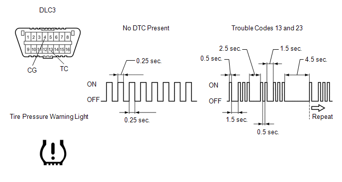
(b) Using SST, connect terminals 13 (TC) and 4 (CG) of the DLC3.
SST: 09843-18040
(c) Turn the ignition switch to ON.
(d) Read and record any DTCs from the tire pressure warning light on the accessory meter. Refer to the illustration as examples of the normal system code and codes 13 and 23.
HINT:
- If the tire pressure warning light does not indicate any DTCs or does
not flash, inspect the tire pressure warning light circuit or TC and CG
terminal circuit.
Trouble Area
See Procedure
Tire pressure warning light circuit
.gif)
TC and CG terminal circuit
- If 2 or more malfunctions are indicated at the same time, the lowest numbered DTC is displayed first.
(e) Refer to the Diagnostic Trouble Code Chart for DTC information (See page
).
(f) After completing the check, turn the ignition switch off and remove SST from the DLC3.
SST: 09843-18040
2. DTC CHECK (USING TECHSTREAM)
(a) Turn the ignition switch off.
(b) Connect the Techstream to the DLC3.
(c) Turn the ignition switch to ON.
(d) Turn the Techstream on.
(e) Enter the following menus: Chassis / Tire Pressure Monitor / Trouble Codes.
(f) Read the DTCs following the prompts on the Techstream.
HINT:
Refer to the Techstream's operator's manual for further details.
3. CLEAR DTC
HINT:
After repairing the malfunctions, clear the DTCs.
(a) Turn the ignition switch off.
(b) Connect the Techstream to the DLC3.
(c) Turn the ignition switch to ON.
(d) Turn the Techstream on.
(e) Enter the following menus: Chassis / Tire Pressure Monitor / Trouble Codes.
(f) Clear the DTCs following the prompts on the Techstream.
HINT:
Refer to the Techstream operator's manual for further details.
 Terminals Of Ecu
TERMINALS OF ECU
1. CHECK TIRE PRESSURE WARNING ECU
HINT:
Inspect the connectors from the back side while the connectors are connected.
(a) Disconnect the L14 tire pressure warning antenna and r ...
 Data List / Active Test
DATA LIST / ACTIVE TEST
1. DATA LIST
HINT:
Using the Techstream to read the Data List allows the values or states of switches,
sensors, actuators and other items to be read without removing any p ...
Other materials about Toyota Venza:
Terminals Of Ecu
TERMINALS OF ECU
1. CHECK TIRE PRESSURE WARNING ECU
HINT:
Inspect the connectors from the back side while the connectors are connected.
(a) Disconnect the L14 tire pressure warning antenna and receiver connector.
(b) Measure the voltage according to the ...
On-vehicle Inspection
ON-VEHICLE INSPECTION
PROCEDURE
1. INSPECT COOLER CONDENSER ASSEMBLY
(a) If the cooler condenser assembly fins are dirty, clean them with water and
dry with compressed air.
NOTICE:
Do not damage the cooler condenser assembly fins.
(b) If any cooler con ...
Cellular Phone Registration Failure
PROCEDURE
1.
CHECK USAGE CONDITION
(a) Check that the vehicle and cellular phone meet the following conditions:
NOTICE:
If changing cellular phone settings, updating software, etc. is necessary, make
sure to obtain the per ...

0.1643