Toyota Venza: Terminals Of Ecu
TERMINALS OF ECU
1. CHECK TIRE PRESSURE WARNING ECU
HINT:
Inspect the connectors from the back side while the connectors are connected.

(a) Disconnect the L14 tire pressure warning antenna and receiver connector.
(b) Measure the voltage according to the value(s) in the table below.
|
Terminal No. (Symbol) |
Wiring Color |
Terminal Description |
Condition |
Specified Condition |
|---|---|---|---|---|
|
D31-12 (RDA) - D31-9 (GND) |
Y - W-B |
Tire pressure warning antenna and receiver signal |
Ignition switch ON |
11 to 14 V |
(c) Connect the L14 tire pressure warning antenna and receiver connector.
(d) Measure the voltage and resistance according to the value(s) in the table below. If the result is not as specified, the ECU may have a malfunction.
|
Terminal No. (Symbol) |
Wiring Color |
Terminal Description |
Condition |
Specified Condition |
|---|---|---|---|---|
|
D31-2 (SPD) - D31-9 (GND) |
P - W-B |
Vehicle speed signal |
Vehicle driving |
Pulse generation (see waveform 1) |
|
D31-3 (TC) - D31-9 (GND) |
BR - W-B |
TC terminal |
Terminal TC not connected |
11 to 14 V |
|
D31-4 (TACH) - D31-9 (GND) |
V - W-B |
Engine speed signal |
Engine running |
Pulse generation (see waveform 2) |
|
D31-5 (IND) - D31-9 (GND) |
LG - W-B |
Tire pressure warning light output signal |
|
Below 0.5 V |
|
After ignition switch is turned to ON, tire pressure warning light illuminates for 3 seconds. |
0.9 to 3.2 V |
|||
|
D31-6 (RF5V) - D31-9 (GND) |
R - W-B |
Tire pressure warning antenna and receiver power source |
Ignition switch ON |
11 to 14 V |
|
D31-7 (IG) - D31-9 (GND) |
GR - W-B |
IG power source |
Ignition switch ON |
11 to 14 V |
|
D31-9 (GND) - Body ground |
W-B - Body ground |
Ground |
Always |
Below 1 Ω |
|
D31-10 (SIL) - D31-9 (GND) |
P - W-B |
Diagnostic communication |
Ignition switch ON |
8 to 14 V |
|
D31-11 (GND2) - D31-9 (GND) |
W - W-B |
Tire pressure warning antenna and receiver ground |
Always |
Below 1 Ω |
|
D31-12 (RDA) - D31-9 (GND) |
Y - W-B |
Tire pressure warning antenna and receiver signal |
Ignition switch ON |
11 to 14 V |
(e) Using an oscilloscope, check waveform 1.
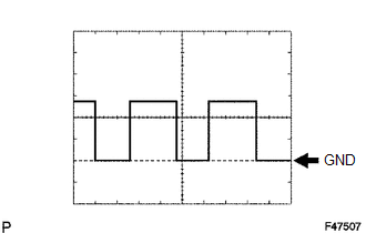 Waveform 1
|
Item |
Content |
|---|---|
|
Terminal |
D31-2 (SPD) - D31-9 (GND) |
|
Tool setting |
5 V/DIV, 20 ms./DIV. |
|
Vehicle condition |
Driving at approximately 20 km/h (12 mph) |
HINT:
The wavelength becomes shorter as the vehicle speed increases.
(f) Using an oscilloscope, check waveform 2.
Waveform 2
|
Item |
Content |
|---|---|
|
Terminal |
D31-4 (TACH) - D31-9 (GND) |
|
Tool setting |
5 V/DIV., 10 ms./DIV. |
|
Vehicle condition |
Idling |
HINT:
The wavelength becomes shorter as the engine speed increases.
 Diagnosis System
DIAGNOSIS SYSTEM
1. CHECK BATTERY VOLTAGE
Standard voltage:
11 to 14 V
If the voltage is below 11 V, recharge the battery before proceeding to the next
step.
2. CHECK DLC3
(a) The ECU uses IS ...
 Dtc Check / Clear
DTC CHECK / CLEAR
1. DTC CHECK (USING SST CHECK WIRE)
(a) Turn the ignition switch off.
(b) Using SST, connect terminals 13 (TC) and 4 (CG) of the DLC3.
SST: 09843-18040
(c) Turn the ignition s ...
Other materials about Toyota Venza:
Relay
On-vehicle Inspection
ON-VEHICLE INSPECTION
PROCEDURE
1. INSPECT HORN RELAY (ENGINE ROOM JUNCTION BLOCK ASSEMBLY)
(a) Remove the engine room junction block assembly from the engine room
relay block (See page ).
...
ABS Warning Light Remains ON
DESCRIPTION
The skid control ECU is connected to the combination meter via CAN communication.
If any of the following is detected, the ABS warning light remains on:
The skid control ECU connector is disconnected from the skid control
ECU.
The ...
System Diagram
SYSTEM DIAGRAM
Communication Method
Transmitting ECU
Receiver
Signal
Communication Method
Main body ECU (Driver Side Junction Block Assembly)
Power back door ECU (Power back door motor ...

0.1695