Toyota Venza: Reassembly
REASSEMBLY
PROCEDURE
1. INSTALL FUEL PUMP ASSEMBLY WITH FILTER
HINT:
Perform "Inspection After Repair" after replacing the fuel pump (See page
.gif) ).
).
|
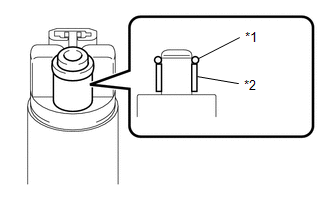
(a) Apply gasoline to a new O-ring. Then install the O-ring and spacer to the fuel pump. Text in Illustration
|
|
|
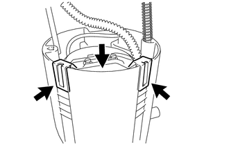
(b) Engage the 5 claws on the fuel filter and install the fuel pump assembly with filter. NOTICE:
|
|
.png)
2. INSTALL FUEL FILTER ASSEMBLY
|
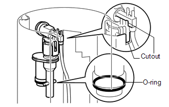
(a) Apply gasoline to a new O-ring and install it to the jet pump. Text in Illustration
|
|
.png)
|
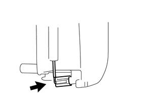
(b) Install the jet pump to the sub-tank as shown in the illustration. |
|
|
(c) Connect the jet pump nozzle to the fuel sub-tank. |
|
|
(d) Install the fuel filter to the sub-tank and attach the 2 claws. |
|
|
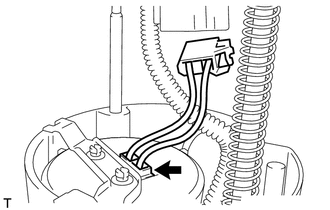
(e) Connect the fuel pump connector to the fuel pump. |
|
3. INSTALL FUEL SUCTION PLATE SUB-ASSEMBLY
(a) Install the spring to the fuel suction plate shaft.
(b) Install the fuel suction plate to the sub-tank.
|
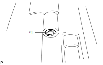
(c) Install a new E-ring. Text in Illustration
|
|
|
(d) Connect the fuel pump connector to the fuel suction plate. |
|
.png)
4. INSTALL FUEL SENDER GAUGE
 Inspection
INSPECTION
PROCEDURE
1. INSPECT FUEL PUMP ASSEMBLY WITH FILTER
(a) Inspect fuel pump resistance.
(1) Measure the resistance according to the value(s) in the table below.
Standard Resistance:
...
 Installation
INSTALLATION
PROCEDURE
1. INSTALL FUEL SUCTION TUBE ASSEMBLY WITH PUMP AND GAUGE
(a) Install a new fuel suction tube set gasket onto the fuel tank.
(b) Connect the fuel tube with the cl ...
Other materials about Toyota Venza:
Operation Check
OPERATION CHECK
1. CHECK BASIC OPERATION
(a) Conditions necessary for the power back door to open:
The power back door main switch is off (switch is not pressed).
The back door is unlocked (except wireless operation).
The vehicle speed is 3 k ...
Removal
REMOVAL
PROCEDURE
1. REMOVE NO. 1 FLOOR UNDER COVER
(a) Disengage the 4 nuts and clip, and remove the No. 1 floor under cover.
Text in Illustration
Nut (attached to under cover)
HINT:
Rotate the clip to disengage it. The 4 ...
Initialization
INITIALIZATION
NOTICE:
Make sure that the front passenger seat is not occupied before performing the
operation.
HINT:
Perform zero point calibration and sensitivity check if any of the following
conditions occur:
The occupant classification ECU ...

0.1481