Toyota Venza: Back Camera Disconnected (C1622)
DESCRIPTION
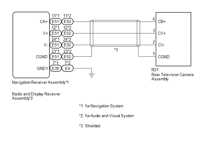
This DTC is stored if the navigation receiver assembly*1 or radio and display receiver assembly*2 judges that the signals or signal lines between the navigation receiver assembly*1 or radio and display receiver assembly*2, and the rear television camera assembly are not normal as a result of its self check.
|
DTC No. |
DTC Detection Condition |
Trouble Area |
|---|---|---|
|
C1622 |
Open or short in the rear television camera assembly signal circuit |
|
*1: for Navigation System
*2: for Audio and Visual System
WIRING DIAGRAM
PROCEDURE
|
1. |
CONFIRM MODEL |
(a) Choose the model to be inspected.
|
Result |
Proceed to |
|---|---|
|
for Navigation System |
A |
|
for Audio and Visual System |
B |
| B | .gif) |
GO TO STEP 5 |
|
.gif)
|
2. |
CHECK HARNESS AND CONNECTOR (NAVIGATION RECEIVER ASSEMBLY - REAR TELEVISION CAMERA ASSEMBLY) |
(a) Disconnect the E51 navigation receiver assembly connector.
(b) Disconnect the R21 rear television camera assembly connector.
(c) Measure the resistance according to the value(s) in the table below.
Standard Resistance:
|
Tester Connection |
Condition |
Specified Condition |
|---|---|---|
|
E51-11 (CA+) - R21-6 (CB+) |
Always |
Below 1 Ω |
|
E51-12 (V+) - R21-3 (CV+) |
Always |
Below 1 Ω |
|
E51-24 (V-) - R21-2 (CV-) |
Always |
Below 1 Ω |
|
E51-23 (CGND) - R21-5 (CGND) |
Always |
Below 1 Ω |
|
E51-11 (CA+) - Body ground |
Always |
10 kΩ or higher |
|
E51-12 (V+) - Body ground |
Always |
10 kΩ or higher |
|
E51-24 (V-) - Body ground |
Always |
10 kΩ or higher |
|
E51-23 (CGND) - Body ground |
Always |
10 kΩ or higher |
| NG | |
REPAIR OR REPLACE HARNESS OR CONNECTOR |
|
|
3. |
INSPECT NAVIGATION RECEIVER ASSEMBLY |
(a) Reconnect the E51 navigation receiver assembly connector.
|
(b) Measure the voltage according to the value(s) in the table below. Standard Voltage:
|
|

| NG | |
REPLACE NAVIGATION RECEIVER ASSEMBLY |
|
|
4. |
INSPECT REAR TELEVISION CAMERA ASSEMBLY |
(a) Reconnect the R21 rear television camera assembly connector.
(b) Using an oscilloscope, check the waveform of the rear television camera assembly.
 Text in Illustration
|
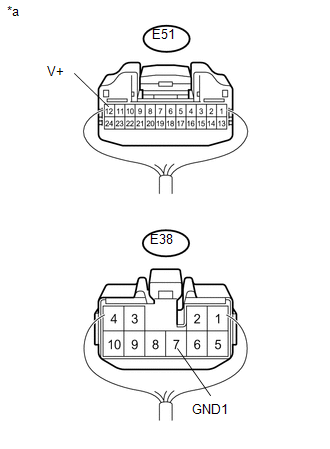
*a |
Component with harness connected (Navigation Receiver Assembly) |
.png)
HINT:
A waterproof connector is used for the rear television camera assembly. Therefore, inspect the waveform at the navigation receiver assembly with the connector connected.
OK:
Waveform is similar to that shown in the illustration.
|
Item |
Content |
|---|---|
|
Measurement terminal |
E51-12 (V+) - E38-7 (GND1) |
|
Measurement setting |
200 mV/DIV., 50 μs./DIV. |
|
Condition |
Ignition switch ON, shift lever in R |
HINT:
- The video waveform changes according to the image sent by the rear television camera assembly.
- The video waveform is constantly output when the ignition switch is turned to ACC.
|
*a |
Waveform 1 (camera lens is not covered, displaying an image) |
|
*b |
Waveform 2 (camera lens is covered, blacking out the screen) |
|
*c |
Synchronization Signal |
|
*d |
Video Waveform |
.png)
| OK | |
REPLACE NAVIGATION RECEIVER ASSEMBLY |
| NG | |
REPLACE REAR TELEVISION CAMERA ASSEMBLY |
|
5. |
CHECK HARNESS AND CONNECTOR (RADIO AND DISPLAY RECEIVER ASSEMBLY - REAR TELEVISION CAMERA ASSEMBLY) |
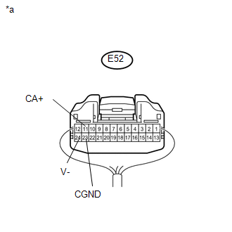
(a) Disconnect the E52 radio and display receiver assembly connector.
(b) Disconnect the R21 rear television camera assembly connector.
(c) Measure the resistance according to the value(s) in the table below.
Standard Resistance:
|
Tester Connection |
Condition |
Specified Condition |
|---|---|---|
|
E52-11 (CA+) - R21-6 (CB+) |
Always |
Below 1 Ω |
|
E52-12 (V+) - R21-3 (CV+) |
Always |
Below 1 Ω |
|
E52-24 (V-) - R21-2 (CV-) |
Always |
Below 1 Ω |
|
E52-23 (CGND) - R21-5 (CGND) |
Always |
Below 1 Ω |
|
E52-11 (CA+) - Body ground |
Always |
10 kΩ or higher |
|
E52-12 (V+) - Body ground |
Always |
10 kΩ or higher |
|
E52-24 (V-) - Body ground |
Always |
10 kΩ or higher |
|
E52-23 (CGND) - Body ground |
Always |
10 kΩ or higher |
| NG | |
REPAIR OR REPLACE HARNESS OR CONNECTOR |
|
|
6. |
INSPECT RADIO AND DISPLAY RECEIVER ASSEMBLY |
(a) Reconnect the E52 radio and display receiver assembly connector.
|
(b) Measure the voltage according to the value(s) in the table below. Standard Voltage:
|
|
| NG | |
REPLACE RADIO AND DISPLAY RECEIVER ASSEMBLY |
|
|
7. |
INSPECT REAR TELEVISION CAMERA ASSEMBLY |
(a) Reconnect the R21 rear television camera assembly connector.
(b) Using an oscilloscope, check the waveform of the rear television camera assembly.
 Text in Illustration
|
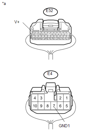
*a |
Component with harness connected (Radio and Display Receiver Assembly) |
HINT:
A waterproof connector is used for the rear television camera assembly. Therefore, inspect the waveform at the radio and display receiver assembly with the connector connected.
OK:
Waveform is similar to that shown in the illustration.
|
Item |
Content |
|---|---|
|
Measurement terminal |
E52-12 (V+) - E4-7 (GND1) |
|
Measurement setting |
200 mV/DIV., 50 μs./DIV. |
|
Condition |
Ignition switch ON, shift lever in R |
HINT:
- The video waveform changes according to the image sent by the rear television camera assembly.
- The video waveform is constantly output when the ignition switch is turned to ACC.
|
*a |
Waveform 1 (camera lens is not covered, displaying an image) |
|
*b |
Waveform 2 (camera lens is covered, blacking out the screen) |
|
*c |
Synchronization Signal |
|
*d |
Video Waveform |
| OK | |
REPLACE RADIO AND DISPLAY RECEIVER ASSEMBLY |
| NG | |
REPLACE REAR TELEVISION CAMERA ASSEMBLY |
 Dtc Check / Clear
DTC CHECK / CLEAR
1. CHECK DTC
(a) Connect the Techstream to the DLC3.
(b) Turn the ignition switch to ON.
(c) Turn the Techstream on.
(d) Enter the following menus: Body Electrical / Navigation ...
 Image from Camera for Rear View Monitor is Abnormal
DESCRIPTION
The video signal of the rear television camera assembly is transmitted
to the navigation receiver assembly*1 or radio and display receiver assembly*2.
*1: for Navigation Sys ...
Other materials about Toyota Venza:
Center Airbag Sensor Assembly Malfunction (B1000/31)
DESCRIPTION
The center airbag sensor assembly consists of a deceleration sensor, safing sensor,
drive circuit, diagnosis circuit, ignition control, etc.
If the center airbag sensor assembly receives signals from the deceleration sensor,
it determines whe ...
Installation
INSTALLATION
PROCEDURE
1. INSTALL TRANSMISSION CONTROL CABLE ASSEMBLY
NOTICE:
Before installing the transmission control cable assembly, check that the park/neutral
position switch and the shift lever are in neutral.
(a) Pass the control cable from the ...
Relay
On-vehicle Inspection
ON-VEHICLE INSPECTION
PROCEDURE
1. INSPECT STARTER RELAY
(a) Measure the resistance according to the value(s) in the table below.
Standard Resistance:
Tester Connection
Condition
...

0.1306