Toyota Venza: Relay
On-vehicle Inspection
ON-VEHICLE INSPECTION
PROCEDURE
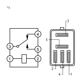
1. REMOVE STOP LIGHT CONTROL (BRK) RELAY
(a) Remove the stop light control (BRK) relay.
|
(b) Measure the resistance according to the value(s) in the table below. Standard Resistance:
|
|
 Removal
REMOVAL
CAUTION / NOTICE / HINT
HINT:
Use the same procedure for the LH side and RH side.
The following procedure is for the LH side.
If the sensor rotor needs to be replaced, repla ...

Other materials about Toyota Venza:
Diagnosis System
DIAGNOSIS SYSTEM
1. DESCRIPTION
(a) The transponder key ECU assembly controls the vehicle's immobiliser system
functions. Immobiliser system data and Diagnostic Trouble Code (DTC) can be read
through the vehicle's Data Link Connector 3 (DLC3).
I ...
Air conditioning filter
The air conditioning filter must be changed regularly to maintain air conditioning
efficiency.
- Removal method
Vehicles with smart key system:
Turn the “ENGINE START STOP” switch off.
Vehicles without smart key system:
Turn the engine switch ...
Washer Nozzle(for Rear Side)
Components
COMPONENTS
ILLUSTRATION
On-vehicle Inspection
ON-VEHICLE INSPECTION
PROCEDURE
1. INSPECT REAR WASHER NOZZLE
(a) With the engine running, check where the washer fluid hits the windshield.
Standard Measurement
Area
...

0.1191