Toyota Venza: Removal
REMOVAL
PROCEDURE
1. REMOVE FRONT WIPER ARM HEAD CAP
.gif)
2. REMOVE FRONT WIPER ARM AND BLADE ASSEMBLY LH
3. REMOVE FRONT WIPER ARM AND BLADE ASSEMBLY RH
4. REMOVE FRONT FENDER TO COWL SIDE SEAL LH
5. REMOVE FRONT FENDER TO COWL SIDE SEAL RH
6. REMOVE COWL TOP VENTILATOR LOUVER SUB-ASSEMBLY
7. REMOVE WINDSHIELD WIPER MOTOR AND LINK ASSEMBLY
8. REMOVE OUTER COWL TOP PANEL
9. REMOVE NO. 1 ENGINE COVER SUB-ASSEMBLY
10. REMOVE VACUUM SWITCHING VALVE ASSEMBLY (for ACIS)
|
(a) Disconnect the 2 vacuum hoses, clamp and connector. |
|
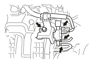
(b) Remove the bolt and vacuum switching valve assembly (for ACIS).
 Inspection
INSPECTION
PROCEDURE
1. INSPECT VACUUM SWITCHING VALVE ASSEMBLY (for ACIS)
(a) Measure the resistance according to the value(s) in the table below.
Text in Illustration
...
 Installation
INSTALLATION
PROCEDURE
1. INSTALL VACUUM SWITCHING VALVE ASSEMBLY (for ACIS)
(a) Install the vacuum switching valve assembly (for ACIS) with the bolt.
Torque:
9.0 N·m {92 kgf·cm ...
Other materials about Toyota Venza:
Assist Map Number Mismatch (C1582)
DESCRIPTION
When an incorrect ECM or brake actuator assembly (skid control ECU) is installed
after the assist map has been recorded in the power steering ECU, then DTC C1582
is stored because the data does not match the vehicle specifications.
...
Terminals Of Ecu
TERMINALS OF ECU
NOTICE:
Turn the ignition switch off before measuring the resistances between
CAN bus main wires and between CAN bus branch wires.
Turn the ignition switch off before inspecting CAN bus wires for a ground
short.
After ...
Data List / Active Test
DATA LIST / ACTIVE TEST
1. DATA LIST
HINT:
Using the Techstream to read the Data List allows the values or states of switches,
sensors, actuators and other items to be read without removing any parts. This non-intrusive
inspection can be very useful bec ...

0.1306