Toyota Venza: Door Courtesy Switch Circuit
DESCRIPTION
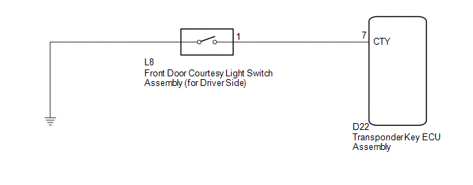
When an additional transponder key is registered, the transponder key ECU assembly detects the front door courtesy light switch assembly (for driver side) open/close condition, and enters the key registration mode.
WIRING DIAGRAM
CAUTION / NOTICE / HINT
NOTICE:
If the transponder key ECU assembly is replaced, register the key and ECU communication
ID (See page .gif) ).
).
PROCEDURE
|
1. |
CHECK HARNESS AND CONNECTOR (FRONT DOOR COURTESY LIGHT SWITCH CIRCUIT) |
|
(a) Disconnect the transponder key ECU assembly connector. |
|
(b) Measure the resistance according to the value(s) in the table below.
Standard Resistance:
|
Tester Connection |
Switch Condition |
Specified Condition |
|---|---|---|
|
D22-7 (CTY) - Body ground |
Courtesy switch pushed (Door closed) |
10 kΩ or higher |
|
D22-7 (CTY) - Body ground |
Courtesy switch free (Door open) |
Below 1 Ω |
|
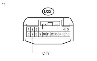
*1 |
Front view of wire harness connector (to Transponder Key ECU Assembly) |
| OK | .gif) |
REPLACE TRANSPONDER KEY ECU ASSEMBLY |
|
.gif)
|
2. |
INSPECT FRONT DOOR COURTESY LIGHT SWITCH ASSEMBLY (for Driver Side) |
|
(a) Remove the front door courtesy light switch assembly (for driver
side) (See page |
|
.png)
(b) Measure the resistance according to the value(s) in the table below.
Standard Resistance:
|
Tester Connection |
Switch Condition |
Specified Condition |
|---|---|---|
|
1 - Switch body |
Courtesy switch pushed (Door closed) |
10 kΩ or higher |
|
1 - Switch body |
Courtesy switch free (Door open) |
Below 1 Ω |
|
*1 |
Component without harness connected (Front Door Courtesy Light Switch Assembly (for Driver Side)) |
|
*2 |
Switch Body |
| OK | |
REPAIR OR REPLACE HARNESS OR CONNECTOR (TRANSPONDER KEY ECU - FRONT DOOR COURTESY LIGHT SWITCH) |
| NG | |
REPLACE FRONT DOOR COURTESY LIGHT SWITCH ASSEMBLY (for Driver Side) |
 Unmatched Encryption Code (B2794)
DESCRIPTION
This DTC is stored when a key with an incomplete key code is inserted into the
ignition key cylinder.
DTC No.
DTC Detection Condition
Trouble Area
...
 Security Indicator Light Circuit
DESCRIPTION
The security indicator light blinks continuously due to a continuous signal received
from the transponder key ECU assembly while in the armed state.
WIRING DIAGRAM
CAUTION / NOTICE ...
Other materials about Toyota Venza:
Installation
INSTALLATION
PROCEDURE
1. INSTALL THROTTLE BODY ASSEMBLY
(a) Install a new gasket to the intake manifold.
(b) Install the fuel tube bracket with the bolt.
Torque:
7.5 N·m {76 kgf ...
Pressure Control Solenoid "A" Performance (Shift Solenoid Valve SL1) (P0746)
SYSTEM DESCRIPTION
The TCM uses the vehicle speed signal and signals from the transmission speed
sensors (NC, NT) to detect the actual gear (1st, 2nd, 3rd, 4th, 5th or 6th gear).
Then the TCM compares the actual gear with the shift schedule in the TCM memo ...
Installation
INSTALLATION
PROCEDURE
1. INSTALL FRONT SEAT ASSEMBLY
(a) Place the front seat assembly in the cabin.
NOTICE:
Be careful not to damage the vehicle body.
(b) Connect each connector under the front seat assembly.
(c) Connect the cable to the negative (-) ...

0.1691