Toyota Venza: Disassembly
DISASSEMBLY
PROCEDURE
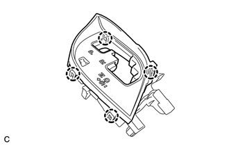
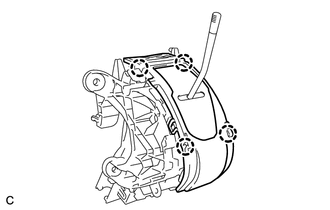
1. REMOVE POSITION INDICATOR HOUSING SUB-ASSEMBLY
(a) Remove the shift lever cap from the position indicator housing sub-assembly.
|
(b) Disengage the 4 claws and remove the position indicator housing sub-assembly. |
|
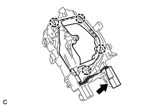
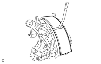
2. REMOVE POSITION INDICATOR LIGHT GUIDE
|
(a) Disengage the 4 claws and remove the position indicator connector and position indicator light guide. |
|
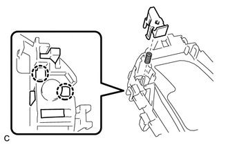
3. REMOVE SHIFT LOCK RELEASE BUTTON
|
(a) Disengage the 2 claws to remove the shift lock release button and compression spring. |
|
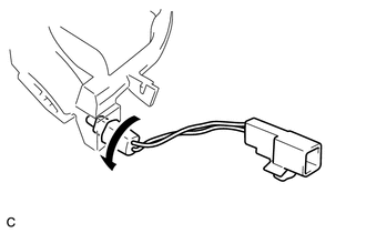
4. REMOVE INDICATOR LIGHT WIRE SUB-ASSEMBLY
|
(a) Remove the indicator light wire sub-assembly from the position indicator light guide. |
|
5. REMOVE POSITION INDICATOR LIGHT BULB
(a) Remove the position indicator light cap from the position indicator light bulb.
(b) Remove the position indicator light bulb from the indicator light wire sub-assembly.
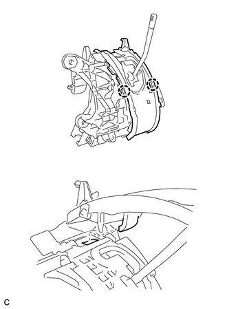
6. REMOVE UPPER POSITION INDICATOR HOUSING
|
(a) Detach the 4 claws and remove the upper position indicator housing from the lower position indicator housing. |
|
7. REMOVE POSITION INDICATOR SLIDE COVER
|
(a) Remove the position indicator slide cover from the lower position indicator housing. |
|
8. REMOVE NO. 2 POSITION INDICATOR SLIDE COVER
(a) Remove the No. 2 position indicator slide cover from the position indicator slide cover.
9. REMOVE LOWER POSITION INDICATOR HOUSING
|
(a) Detach the 2 claws and remove the lower position indicator housing from the shift lock control unit assembly. |
|
10. REMOVE SHIFT LOCK CONTROL COMPUTER SUB-ASSEMBLY
|
(a) Disconnect the connector from the shift lock control computer sub-assembly. |
|
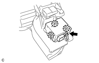
(b) Detach the 3 claws and remove the shift lock control computer sub-assembly.
 On-vehicle Inspection
ON-VEHICLE INSPECTION
PROCEDURE
1. INSPECT SHIFT LOCK CONTROL UNIT ASSEMBLY
(a) Inspect the shift lock operation.
(1) Move the shift lever to P.
(2) Turn the ignition switch off.
(3) Check that ...
 Removal
REMOVAL
PROCEDURE
1. DISCONNECT CABLE FROM NEGATIVE BATTERY TERMINAL
NOTICE:
When disconnecting the cable, some systems need to be initialized after the cable
is reconnected (See page ).
2. RE ...
Other materials about Toyota Venza:
Cancellation of 4WD Control (C1299/99)
DESCRIPTION
If wheel slip continues, differential control will be disabled when
the torque-distribution ratio of the differential clutch exceeds the set
value and a malfunction in the output of the wheel speed sensors, etc. occurs.
If a ...
Camshaft Position "A" - Timing Over-Advanced or System Performance (Bank 1)
(P0011,P0012)
DESCRIPTION
Refer to DTC P0010 (See page ).
DTC No.
DTC Detection Condition
Trouble Area
P0011
The valve timing is stuck at a certain value when in the advance range
(1 trip detection logic).
...
Multi-information display (LCD type)
The multi-information display presents the driver with a variety of driving-related
data, including the clock and current outside temperature.
• Clock
Indicates and sets the time.
• Outside temperature
Indicates the outside temperature.
The temper ...

0.1392