Toyota Venza: Removal
REMOVAL
PROCEDURE
1. DISCONNECT CABLE FROM NEGATIVE BATTERY TERMINAL
NOTICE:
When disconnecting the cable, some systems need to be initialized after the cable
is reconnected (See page .gif) ).
).
2. REMOVE UPPER CONSOLE PANEL SUB-ASSEMBLY (w/o Seat Heater System)
3. REMOVE UPPER CONSOLE PANEL SUB-ASSEMBLY (w/ Seat Heater System)
4. REMOVE NO. 2 CONSOLE BOX CARPET
5. REMOVE CONSOLE BOX ASSEMBLY
6. REMOVE AIR CONDITIONING CONTROL ASSEMBLY
7. REMOVE FRONT DOOR SCUFF PLATE LH
8. REMOVE COWL SIDE TRIM SUB-ASSEMBLY LH
9. REMOVE LOWER NO. 1 INSTRUMENT PANEL FINISH PANEL
10. REMOVE FRONT DOOR SCUFF PLATE RH
11. REMOVE COWL SIDE TRIM SUB-ASSEMBLY RH
12. REMOVE NO. 2 INSTRUMENT PANEL UNDER COVER SUB-ASSEMBLY
13. REMOVE LOWER INSTRUMENT PANEL SUB-ASSEMBLY
14. REMOVE SHIFT LEVER KNOB SUB-ASSEMBLY
15. REMOVE POSITION INDICATOR HOUSING ASSEMBLY
16. REMOVE CONSOLE BOX SUB-ASSEMBLY
17. REMOVE SHIFT LEVER ASSEMBLY
(a) Move the shift lever to N.
|
(b) Disconnect the 2 connectors. |
|
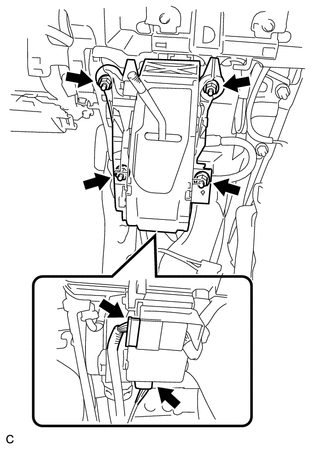
(c) Remove the 4 nuts and shift lever assembly.
|
(d) Disconnect the end of the transmission control cable assembly from the shift lever assembly. |
|
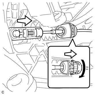
(e) Turn the lock nut counterclockwise. While holding the lock nut, disconnect the transmission control cable from the shift lever retainer.
 Disassembly
DISASSEMBLY
PROCEDURE
1. REMOVE POSITION INDICATOR HOUSING SUB-ASSEMBLY
(a) Remove the shift lever cap from the position indicator housing sub-assembly.
(b) Disengage the 4 claws and re ...
 Inspection
INSPECTION
PROCEDURE
1. INSPECT SHIFT LOCK CONTROL UNIT ASSEMBLY (w/o Smart Key System)
(a) Measure the voltage according to the value(s) in the table below.
Text in Illustration
...
Other materials about Toyota Venza:
Data List / Active Test
DATA LIST / ACTIVE TEST
1. DATA LIST
HINT:
Using the Techstream to read the Data List allows the values or states of switches,
sensors, actuators and other items to be read without removing any parts. This non-intrusive
inspection can be very useful bec ...
Oxygen Sensor Heater Control Circuit Low (Bank 1 Sensor 2) (P0037,P0038,P0141,P102D)
DESCRIPTION
Refer to DTC P0136 (See page ).
HINT:
When any of these DTCs are stored, the ECM enters fail-safe mode. The
ECM turns off the heated oxygen sensor heater in fail-safe mode. Fail-safe
mode continues until the ignition switch is t ...
Installation
INSTALLATION
PROCEDURE
1. INSTALL INSTRUMENT PANEL WIRE ASSEMBLY
(a) Connect the vent hole connector of the instrument panel wire to the
front passenger airbag assembly.
Text in Illustration
*1
Vent Hol ...

0.1712