Toyota Venza: Inspection
INSPECTION
PROCEDURE
1. INSPECT FRONT LOWER BALL JOINT
|
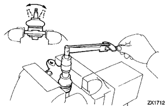
(a) Inspect the turning torque of the ball joint. (1) Secure the front lower ball joint in a vise using aluminum plates. (2) Install the nut to the front lower ball joint stud. (3) Using a torque wrench, turn the nut continuously at a rate of 3 to 5 seconds per turn and take the torque reading on the 5th turn. Turning torque: 0.7 to 4.5 N*m (7 to 46 kgf*cm, 6.2 to 40 in.*lbf) If the turning torque is not within the specified range, replace the front lower ball joint with a new one. |
|
(b) Inspect the dust cover.
(1) Check that the dust cover is not cracked and that there is no grease on it.
 Components
COMPONENTS
ILLUSTRATION
...
 Removal
REMOVAL
CAUTION / NOTICE / HINT
HINT:
Use the same procedure for the LH side and RH side.
The following procedure listed is for the LH side.
PROCEDURE
1. REMOVE FRONT WHEEL
2. ...
Other materials about Toyota Venza:
Installation
INSTALLATION
PROCEDURE
1. INSTALL REAR SEAT INNER BELT ASSEMBLY RH
(a) Install the rear seat inner belt assembly RH with the bolt.
Torque:
42 N·m {428 kgf·cm, 31 ft·lbf}
2. INSTALL REAR SE ...
Combination Meter
Components
COMPONENTS
ILLUSTRATION
Disassembly
DISASSEMBLY
PROCEDURE
1. REMOVE COMBINATION METER GLASS
(a) Disengage the 9 claws to remove the combination meter glass.
Removal
REMOVAL
...
Back Door Opener Switch
Components
COMPONENTS
ILLUSTRATION
Removal
REMOVAL
PROCEDURE
1. REMOVE BACK DOOR PANEL TRIM ASSEMBLY
2. REMOVE REAR LIGHT ASSEMBLY LH
3. REMOVE REAR LIGHT ASSEMBLY RH
HINT:
Use the same procedure for the RH side and LH side.
4. REMOVE BA ...

0.1622