Toyota Venza: Components
COMPONENTS
ILLUSTRATION
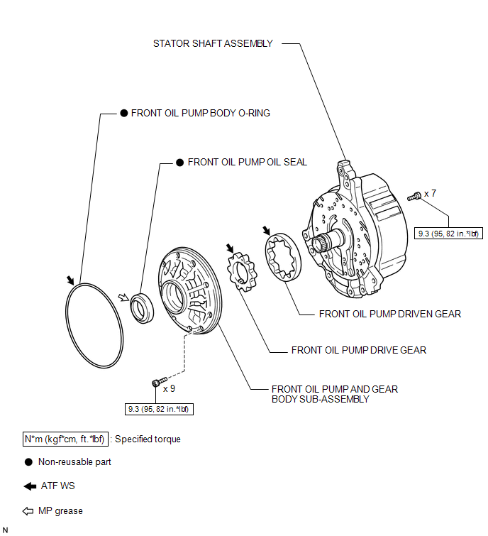
 Oil Pump
...
 Disassembly
DISASSEMBLY
PROCEDURE
1. INSPECT FRONT OIL PUMP AND GEAR BODY SUB-ASSEMBLY
2. REMOVE STATOR SHAFT ASSEMBLY
(a) Using a "TORX" wrench (T30), remove the 16 bolts and stator s ...
Other materials about Toyota Venza:
Precaution
PRECAUTION
1. PRECAUTION FOR VEHICLE WITH SRS AIRBAG AND SEAT BELT PRETENSIONER
(a) Some operations in this section may affect the SRS airbags. Prior to performing
the corresponding operations, read the precautions regarding the SRS airbags (See
page ). ...
Back Door Lock
Components
COMPONENTS
ILLUSTRATION
Removal
REMOVAL
PROCEDURE
1. REMOVE BACK DOOR PANEL TRIM ASSEMBLY
2. REMOVE BACK DOOR LOCK ASSEMBLY
(a) Disconnect the connector.
(b) Disengage the c ...
Brake Override System
DESCRIPTION
When the vehicle is being driven, depressing the accelerator pedal sensor assembly
and brake pedal will activate the brake override system to restrict driving torque.
The conditions for activating the brake override system as well as the items ...

0.131