
Toyota Venza: Disassembly
DISASSEMBLY
PROCEDURE
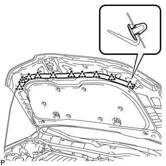
1. REMOVE HOOD TO RADIATOR SUPPORT SEAL
|
(a) Using a clip remover, disengage the 10 clips and remove the hood to radiator support seal. |
|
2. REMOVE HOOD INSULATOR
|
(a) Using a clip remover, remove the 10 clips. |
|
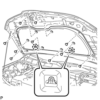
(b) Disengage the 2 claws and remove the hood insulator.
3. REMOVE FRONT WASHER NOZZLE SUB-ASSEMBLY
.gif)
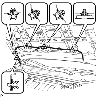
4. DISCONNECT WASHER HOSE ASSEMBLY
|
(a) Using a clip remover, disengage the 5 clips and disconnect the washer hose assembly. |
|
 Hood
Hood
...
 On-vehicle Inspection
ON-VEHICLE INSPECTION
PROCEDURE
1. INSPECT HOOD SUB-ASSEMBLY
(a) Check that the clearance measurements of areas *1 through *4 are within each
standard range.
Standard Clearance
Area ...
Other materials about Toyota Venza:
ABS Warning Light does not Come ON
DESCRIPTION
The skid control ECU is connected to the combination meter via CAN communication.
WIRING DIAGRAM
Refer to ABS Warning Light Remains ON (See page
).
PROCEDURE
1.
CHECK CAN COMMUNICATION SYSTEM
(a) Check if a C ...
Radio Receiver Power Source Circuit
DESCRIPTION
This is the power source circuit to operate the radio and display receiver assembly.
WIRING DIAGRAM
CAUTION / NOTICE / HINT
NOTICE:
Inspect the fuses for circuits related to this system before performing the following
inspection procedure. ...
Installation
INSTALLATION
PROCEDURE
1. INSPECT TORQUE CONVERTER ASSEMBLY
2. INSTALL TORQUE CONVERTER ASSEMBLY
(a) Engage the splines of the input shaft and turbine runner.
(b) Engage the splines o ...

0.1569