Toyota Venza: Removal
REMOVAL
PROCEDURE
1. DRAIN DIFFERENTIAL OIL
|
(a) Using a 10 mm hexagon wrench, remove the rear differential carrier cover plug and gasket. |
|
.png)
|
(b) Using a 10 mm hexagon wrench, remove the rear differential drain plug and gasket to drain the differential oil. |
|
.png)
2. REMOVE REAR WHEELS
3. REMOVE CENTER EXHAUST PIPE ASSEMBLY
(a) Remove the center exhaust pipe assembly.
HINT:
Refer to the instructions for Removal of the exhaust pipe (See page
.gif) for 2GR-FE,
for 2GR-FE,
for 1AR-FE).
4. REMOVE PROPELLER WITH CENTER BEARING SHAFT ASSEMBLY
5. SEPARATE REAR SPEED SENSOR LH
6. SEPARATE REAR SPEED SENSOR RH
7. REMOVE REAR AXLE SHAFT NUT LH
8. REMOVE REAR AXLE SHAFT NUT RH
9. SEPARATE NO. 3 PARKING BRAKE CABLE ASSEMBLY
10. SEPARATE NO. 2 PARKING BRAKE CABLE ASSEMBLY
11. REMOVE NO. 1 FLOOR UNDER COVER
12. REMOVE REAR STRUT ROD ASSEMBLY LH
13. REMOVE REAR STRUT ROD ASSEMBLY RH
14. REMOVE REAR HEIGHT CONTROL SENSOR SUB-ASSEMBLY (w/ HID Headlight System)
15. REMOVE REAR NO. 2 SUSPENSION ARM ASSEMBLY LH
16. REMOVE REAR NO. 2 SUSPENSION ARM ASSEMBLY RH
17. SEPARATE REAR NO. 1 SUSPENSION ARM ASSEMBLY LH
18. SEPARATE REAR NO. 1 SUSPENSION ARM ASSEMBLY RH
19. REMOVE REAR DRIVE SHAFT ASSEMBLY LH
20. REMOVE REAR DRIVE SHAFT SNAP RING LH
21. REMOVE REAR DRIVE SHAFT ASSEMBLY RH
22. REMOVE REAR DRIVE SHAFT SNAP RING RH
23. SEPARATE NO. 3 FLOOR WIRE (w/ HID Headlight System)
24. SEPARATE FRAME WIRE
25. REMOVE REAR SUSPENSION MEMBER
26. REMOVE REAR DIFFERENTIAL CARRIER ASSEMBLY WITH DIFFERENTIAL SUPPORT
|
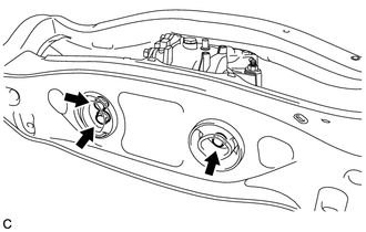
(a) Remove the 2 bolts and 2 nuts. HINT: The nuts have tabs to prevent them from rotating. |
|
|
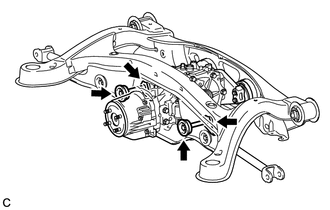
(b) Remove the 3 rear mounting bolts and rear differential carrier assembly with differential support from the rear suspension member assembly. |
|
27. REMOVE DIFFERENTIAL SUPPORT
|
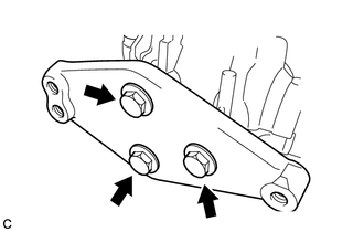
(a) Remove the 3 bolts and differential support. |
|
28. REMOVE REAR NO. 1 DIFFERENTIAL SUPPORT
|
(a) Remove the 2 bolts, 2 nuts and rear No. 1 differential support. HINT: The nuts have tabs to prevent them from rotating. |
|
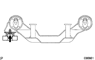
29. REMOVE REAR DIFFERENTIAL DYNAMIC DAMPER
HINT:
This step should be performed only when the rear differential dynamic damper is being replaced.
|
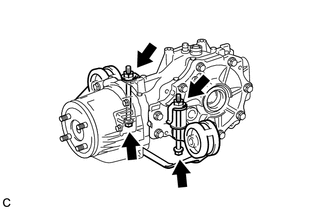
(a) Remove the bolt and rear differential dynamic damper. |
|
 Components
COMPONENTS
ILLUSTRATION
ILLUSTRATION
ILLUSTRATION
ILLUSTRATION
ILLUSTRATION
ILLUSTRATION
ILLUSTRATION
ILLUSTRATION
ILLUSTRATION
...
 Disassembly
DISASSEMBLY
CAUTION / NOTICE / HINT
HINT:
Use an overhaul stand as necessary.
PROCEDURE
1. REMOVE REAR DIFFERENTIAL FILLER PLUG
(a) Remove the rear differential filler plug and gasket ...
Other materials about Toyota Venza:
On-vehicle Inspection
ON-VEHICLE INSPECTION
PROCEDURE
1. INSPECT CAMSHAFT TIMING OIL CONTROL VALVE ASSEMBLY
(a) Connect the Techstream to the DLC3.
(b) Start the engine and turn the Techstream on.
(c) Inspect the oil control valve (for intake camshaft).
(1) Enter the followin ...
Driver Side Power Window does not Operate with Power Window Master Switch
DESCRIPTION
When the engine is running or the ignition switch is ON, the power window regulator
motor assembly (for driver side) is operated by the power window regulator master
switch assembly. The power window regulator motor assembly (for driver side) ...
Voice is not Recognized
PROCEDURE
1.
CHECK CONDITION
(a) Check if the system voice recognition level is low when recognizing a particular
voice.
Result
Proceed to
System voice recognition level is low only fo ...

0.1153