Toyota Venza: Relay
On-vehicle Inspection
ON-VEHICLE INSPECTION
PROCEDURE
1. FAN NO. 1 RELAY
|
(a) Remove the relay from the engine room relay block. |
|
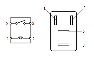
(b) Measure the resistance according to the value(s) in the table below.
Standard Resistance:
|
Tester Connection |
Condition |
Specified Condition |
|---|---|---|
|
3 - 5 |
Battery voltage is not applied between terminals 1 and 2 |
10 kΩ or higher |
|
3 - 5 |
Battery voltage is applied between terminals 1 and 2 |
Below 1 Ω |
- If the result is not as specified, replace the relay.
(c) Install the relay to the engine room relay block.
2. FAN NO. 2 RELAY
|
(a) Remove the relay from the engine room relay block. |
|
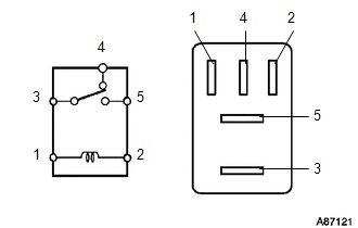
(b) Measure the resistance according to the value(s) in the table below.
Standard Resistance:
|
Tester Connection |
Condition |
Specified Condition |
|---|---|---|
|
3 - 4 |
Battery voltage is not applied between terminals 1 and 2 |
Below 1 Ω |
|
3 - 5 |
Battery voltage is not applied between terminals 1 and 2 |
10 kΩ or higher |
|
3 - 4 |
Battery voltage is applied between terminals 1 and 2 |
10 kΩ or higher |
|
3 - 5 |
Battery voltage is applied between terminals 1 and 2 |
Below 1 Ω |
- If the result is not as specified, replace the relay.
(c) Install the relay.
3. FAN NO. 3 RELAY
|
(a) Remove the relay from the engine room relay block. |
|
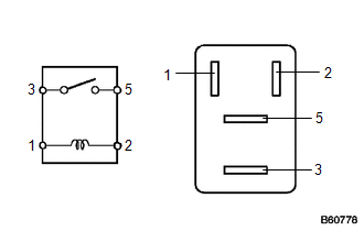
(b) Measure the resistance according to the value(s) in the table below.
Standard Resistance:
|
Tester Connection |
Condition |
Specified Condition |
|---|---|---|
|
3 - 5 |
Battery voltage is not applied between terminals 1 and 2 |
10 kΩ or higher |
|
3 - 5 |
Battery voltage is applied between terminals 1 and 2 |
Below 1 Ω |
- If the result is not as specified, replace the relay.
(c) Install the relay.
 Removal
REMOVAL
PROCEDURE
1. REMOVE NO. 1 ENGINE UNDER COVER
2. REMOVE NO. 2 ENGINE UNDER COVER
3. DRAIN ENGINE COOLANT
4. REMOVE COOL AIR INTAKE DUCT SEAL
5. REMOVE INLET AIR CLEANER ASSEMBLY
...
 Thermostat
...
Other materials about Toyota Venza:
Installation
INSTALLATION
PROCEDURE
1. INSTALL POWER SEAT SWITCH
(a) Install the power seat switch with the 3 screws.
(b) Connect the connector.
2. INSTALL FRONT SEAT CUSHION SHIELD ASSEMBLY
3. INSTALL SLID ...
Removal
REMOVAL
PROCEDURE
1. REMOVE REAR WHEELS
2. REMOVE REAR STABILIZER LINK ASSEMBLY LH
(a) Remove the nut and separate the rear stabilizer link assembly LH
from the rear stabilizer bar.
Text in Illustration
*1
...
Inspection
INSPECTION
PROCEDURE
1. INSPECT FRONT NO. 2 SPEAKER ASSEMBLY (for 6 Speakers)
(a) With the speaker installed, check that there is no looseness or other abnormalities.
(b) Check that there is no foreign matter in the speaker, no tears on the speaker
cone ...

0.1735