Toyota Venza: Cruise Control Switch Circuit
DESCRIPTION
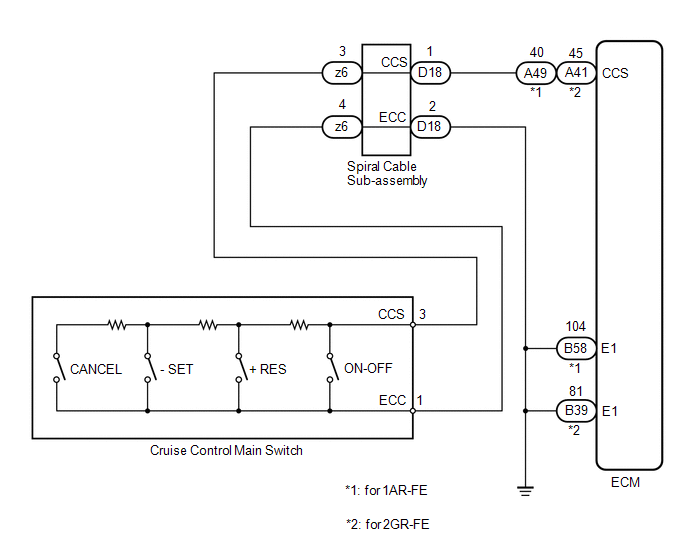
The cruise control main switch operates 7 functions: SET, -, TAP-DOWN, RES, +, TAP-UP, and CANCEL. The SET, TAP-DOWN, and - functions, and the RES, TAP-UP, and + functions are operated with the same switch. The cruise control main switch is an automatic return type switch which turns on only while it is being operated in the direction of each arrow and turns off after being released. The internal contact point of the cruise control main switch is turned on with the switch operation. Then the ECM reads the voltage value that has been changed by the switch operation to control SET, -, RES, +, and CANCEL.
WIRING DIAGRAM
PROCEDURE
|
1. |
READ VALUE USING TECHSTREAM (CRUISE CONTROL MAIN SWITCH OPERATION) |
|
(a) Connect the Techstream to the DLC3. |
|
(b) Turn the ignition switch to ON.
(c) Turn the Techstream on.
(d) Enter the following menus: Powertrain / Cruise Control / Data List.
(e) Check the Data List for proper functioning of the cruise control main switch.
Cruise Control (ECM)|
Tester Display |
Measurement Item/Range |
Normal Condition |
Diagnostic Note |
|---|---|---|---|
|
Main SW M-CPU |
Main switch signal (Main CPU) / ON or OFF |
ON: Main switch on OFF: Main switch off |
- |
|
Cancel Switch |
CANCEL switch signal / ON or OFF |
ON: CANCEL switch on OFF: CANCEL switch off |
- |
|
SET/COAST Switch |
- / SET switch signal / ON or OFF |
ON: - / SET switch on OFF: - / SET switch off |
- |
|
RES/ACC Switch |
+ / RES switch signal / ON or OFF |
ON: + / RES switch on OFF: + / RES switch off |
- |
OK:
The display changes as shown above according to cruise control main switch operation.
Result|
Result |
Proceed to |
|---|---|
|
OK |
A |
|
NG (All items are defective) |
B |
|
NG (1 to 3 items are defective) |
C |
|
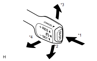
*1 |
ON/OFF |
|
*2 |
- SET |
|
*3 |
+ RES |
|
*4 |
CANCEL |
| A | .gif) |
PROCEED TO NEXT SUSPECTED AREA SHOWN IN PROBLEM SYMPTOMS TABLE |
| C | |
REPLACE CRUISE CONTROL MAIN SWITCH |
|
.gif)
|
2. |
INSPECT CRUISE CONTROL MAIN SWITCH |
(a) Remove the cruise control main switch (See page
.gif) ).
).
(b) Measure the resistance according to the value(s) in the table below.
.png) Text in Illustration
Text in Illustration
|
*1 |
Component without harness connected (Cruise Control Main Switch) |
*2 |
Main Switch |
|
*3 |
Lever |
*4 |
ON/OFF |
|
*5 |
- SET |
*6 |
+ RES |
|
*7 |
CANCEL |
- |
- |
Standard Resistance:
|
Tester Connection |
Switch Condition |
Specified Condition |
|---|---|---|
|
1 (ECC) - 3 (CCS) |
Main Switch off |
1 MΩ or higher |
|
Main Switch on |
Below 2.5 Ω |
|
|
+ RES |
235 to 245 Ω |
|
|
- SET |
617 to 643 Ω |
|
|
CANCEL |
1509 to 1571 Ω |
(c) Reinstall the cruise control main switch (See page
).
| NG | |
REPLACE CRUISE CONTROL MAIN SWITCH |
|
|
3. |
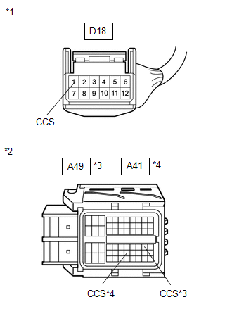
CHECK HARNESS AND CONNECTOR (CRUISE CONTROL MAIN SWITCH - SPIRAL CABLE SUB-ASSEMBLY) |
(a) Remove the steering pad (See page ).
(b) Disconnect the cruise control main switch connector.
(c) Disconnect the spiral cable sub-assembly connector.
(d) Measure the resistance according to the value(s) in the table below.
Standard Resistance:
|
Tester Connection |
Condition |
Specified Condition |
|---|---|---|
|
Cruise control main switch side connector terminal 3 (CCS) - z6-3 (CCS) |
Always |
Below 1 Ω |
|
Cruise control main switch side connector terminal 1 (ECC) - z6-4 (ECC) |
Always |
Below 1 Ω |
|
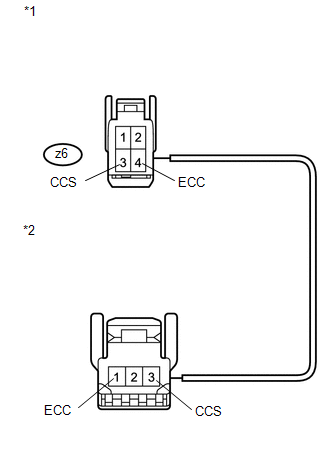
*1 |
Front view of wire harness connector (to Spiral Cable Sub-assembly) |
|
*2 |
Front view of wire harness connector (to Cruise Control Main Switch) |
(e) Reconnect the spiral cable sub-assembly connector.
(f) Reconnect the cruise control main switch connector.
(g) Reinstall the steering pad (See page ).
| NG | |
REPAIR OR REPLACE HARNESS OR CONNECTOR (CRUISE CONTROL MAIN SWITCH - SPIRAL CABLE SUB-ASSEMBLY) |
|
|
4. |
INSPECT SPIRAL CABLE SUB-ASSEMBLY |
NOTICE:
The spiral cable sub-assembly is an important part of the SRS airbag system. Incorrect removal or installation of the spiral cable sub-assembly may cause airbag deployment. Be sure to read the page shown in the brackets.
HINT:
- Removal (See page )
- Installation (See page )
(a) Remove the spiral cable sub-assembly.
(b) Measure the resistance according to the value(s) in the table below.
Standard Resistance:
|
Tester Connection |
Condition |
Specified Condition |
|---|---|---|
|
z6-3 (CCS) - D18-1 (CCS) |
The spiral cable sub-assembly is centered |
Below 1 Ω |
|
The spiral cable sub-assembly position is 2.5 rotations to the left |
||
|
The spiral cable sub-assembly position is 2.5 rotations to the right |
||
|
z6-4 (ECC) - D18-2 (ECC) |
The spiral cable sub-assembly is centered |
Below 1 Ω |
|
The spiral cable sub-assembly position is 2.5 rotations to the left |
||
|
The spiral cable sub-assembly position is 2.5 rotations to the right |
HINT:
The spiral cable makes a maximum of approximately 5 rotations.
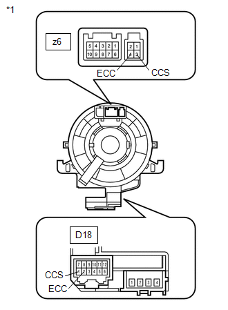
Text in Illustration|
*1 |
Component without harness connected (Spiral Cable Sub-assembly) |
(c) Reinstall the spiral cable sub-assembly.
| NG | |
REPLACE SPIRAL CABLE SUB-ASSEMBLY |
|
|
5. |
CHECK HARNESS AND CONNECTOR (SPIRAL CABLE SUB-ASSEMBLY - ECM) |
(a) Disconnect the ECM connector.
(b) Disconnect the spiral cable sub-assembly connector.
|
(c) Measure the resistance according to the value(s) in the table below. Standard Resistance (Check for Open): For 1AR-FE
Standard Resistance (Check for Short): For 1AR-FE
|
|
|
*1 |
Front view of wire harness connector (to Spiral Cable Sub-assembly) |
|
*2 |
Front view of wire harness connector (to ECM) |
|
*3 |
for 1AR-FE |
|
*4 |
for 2GR-FE |
(d) Reconnect the spiral cable sub-assembly connector.
(e) Reconnect the ECM connector.
| NG | |
REPAIR OR REPLACE HARNESS OR CONNECTOR (SPIRAL CABLE SUB-ASSEMBLY - ECM) |
|
|
6. |
CHECK HARNESS AND CONNECTOR (SPIRAL CABLE SUB-ASSEMBLY - BODY GROUND) |
|
(a) Disconnect the spiral cable sub-assembly connector. Text in Illustration
|
|
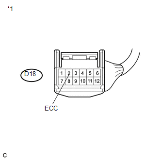
(b) Measure the resistance according to the value(s) in the table below.
Standard Resistance:
|
Tester Connection |
Condition |
Specified Condition |
|---|---|---|
|
D18-2 (ECC) - Body ground |
Always |
Below 1 Ω |
|
Result |
Proceed to |
|---|---|
|
NG |
A |
|
OK (for 1AR-FE) |
B |
|
OK (for 2GR-FE) |
C |
(c) Reconnect the spiral cable sub-assembly connector.
| A | |
REPAIR OR REPLACE HARNESS OR CONNECTOR (SPIRAL CABLE SUB-ASSEMBLY - BODY GROUND) |
| B | |
REPLACE ECM |
| C | |
REPLACE ECM |
 Cruise Control Input Circuit (P0575)
DESCRIPTION
This DTC indicates the internal abnormalities of the ECM.
DTC
DTC Detection Condition
Trouble Area
P0575
When both of the fol ...
 Cruise Main Indicator Light Circuit
DESCRIPTION
The ECM detects a cruise control main switch signal and sends it to
the combination meter assembly through CAN. Then the CRUISE main indicator
light comes on.
The CRUIS ...
Other materials about Toyota Venza:
Removal
REMOVAL
PROCEDURE
1. REMOVE FRONT DOOR SCUFF PLATE LH
(a) Disengage the 3 clips, 7 claws and guide, and remove the front door
scuff plate LH.
2. REMOVE COWL SIDE TRIM SUB-ASSEMBLY LH
...
Replacement
REPLACEMENT
CAUTION / NOTICE / HINT
HINT:
Use the same procedure for the RH side and LH side.
The procedure listed below is for the LH side.
PROCEDURE
1. DRAIN DIFFERENTIAL OIL
2. REMOVE REAR WHEEL
3. REMOVE CENTER EXHAUST PIPE ASSE ...
Reassembly
REASSEMBLY
PROCEDURE
1. INSTALL NO. 1 INSTRUMENT PANEL PIN
(a) Install the 2 No. 1 instrument panel pins with the 2 screws <E> or
<F>.
2. INSTALL GLOVE BOX LIGHT ASSEMBLY
...

0.1623