Toyota Venza: Removal
REMOVAL
PROCEDURE
1. DISCONNECT CABLE FROM NEGATIVE BATTERY TERMINAL
CAUTION:
Wait at least 90 seconds after disconnecting the cable from the negative (-) battery terminal to disable the SRS system.
NOTICE:
When disconnecting the cable, some systems need to be initialized after the cable
is reconnected (See page .gif) ).
).
2. REMOVE FRONT SEAT ASSEMBLY LH
HINT:
Refer to the instructions for Removal of the front seat assembly.
- for Manual Seat: See page
- for Power Seat: See page
3. REMOVE UPPER CONSOLE PANEL SUB-ASSEMBLY (w/o Seat Heater System)
4. REMOVE UPPER CONSOLE PANEL SUB-ASSEMBLY (w/ Seat Heater System)
5. REMOVE NO. 2 CONSOLE BOX CARPET
6. REMOVE CONSOLE BOX ASSEMBLY
7. REMOVE AIR CONDITIONING CONTROL ASSEMBLY
8. REMOVE FRONT DOOR SCUFF PLATE LH
9. REMOVE COWL SIDE TRIM SUB-ASSEMBLY LH
10. REMOVE LOWER NO. 1 INSTRUMENT PANEL FINISH PANEL
11. REMOVE FRONT DOOR SCUFF PLATE RH
12. REMOVE COWL SIDE TRIM SUB-ASSEMBLY RH
13. REMOVE NO. 2 INSTRUMENT PANEL UNDER COVER SUB-ASSEMBLY
14. REMOVE LOWER INSTRUMENT PANEL SUB-ASSEMBLY
15. REMOVE SHIFT LEVER KNOB SUB-ASSEMBLY
16. REMOVE POSITION INDICATOR HOUSING ASSEMBLY
17. REMOVE CONSOLE BOX SUB-ASSEMBLY
18. SEPARATE PARKING BRAKE PEDAL ASSEMBLY
(a) Turn back the floor carpet.
|
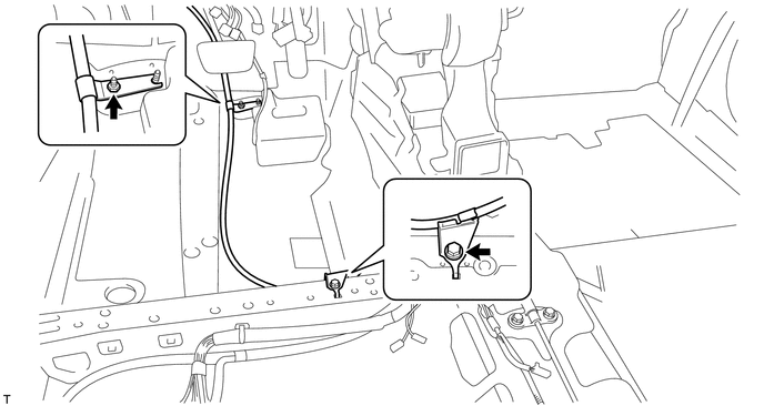
(b) Disconnect the heated oxygen sensor connector and disengage the 2 clamps (for 2GR-FE). |
|
.png)
(c) Remove the bolt and nut, and separate the No. 1 parking brake cable assembly from the body.
|
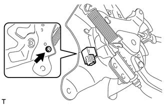
(d) Disconnect the parking brake switch connector. |
|
.png)
|
(e) Remove the 3 nuts and separate the parking brake pedal assembly from the body. |
|
.png)
19. REMOVE PARKING BRAKE SWITCH ASSEMBLY
|
(a) Remove the screw and parking brake switch assembly. |
|
 Components
COMPONENTS
ILLUSTRATION
ILLUSTRATION
ILLUSTRATION
ILLUSTRATION
...
 Inspection
INSPECTION
PROCEDURE
1. INSPECT PARKING BRAKE SWITCH ASSEMBLY
(a) Measure the resistance according to the value(s) in the table below.
Standard Resistance:
Tester ...
Other materials about Toyota Venza:
One or more Power Seat Motors do not Operate
DESCRIPTION
Signals are input into the position control ECU and switch assembly. The built-in
ECU manages the signals received from the position control ECU and switch assembly,
and operates each motor. If the position control ECU and switch assembly rece ...
Cancellation of 4WD Control (C1299/99)
DESCRIPTION
If wheel slip continues, differential control will be disabled when
the torque-distribution ratio of the differential clutch exceeds the set
value and a malfunction in the output of the wheel speed sensors, etc. occurs.
If a ...
SFR Solenoid Circuit (C0226/21,C0236/22,C0246/23,C0256/24,C1225/25-C1228/28)
DESCRIPTION
These solenoids turn on when signals are received from the skid control ECU and
they control the pressure acting on the wheel cylinders to control the braking force.
DTC Code
DTC Detection Condition
Trouble Area ...

0.1221