Toyota Venza: Control Module Communication Bus OFF (U0073/94,U0100/65,U0123/62,U0124/95,U0126/63)
DESCRIPTION
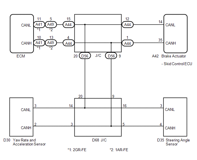
The skid control ECU receives the signals from the ECM, steering angle sensor, and yaw rate and acceleration sensor via the CAN communication system.
|
DTC Code |
DTC Detection Condition |
Trouble Area |
|---|---|---|
|
U0073/94 |
Any of the following is detected:
|
CAN communication system |
|
U0100/65 |
Either of the following is detected:
|
CAN communication system (Skid control ECU to ECM) |
|
U0123/62 |
Either of the following is detected:
|
CAN communication system (Skid control ECU to yaw rate and acceleration sensor) |
|
U0124/95 |
Either of the following is detected:
|
CAN communication system (Skid control ECU to yaw rate and acceleration sensor) |
|
U0126/63 |
Either of the following is detected:
|
CAN communication system (Skid control ECU to steering angle sensor) |
WIRING DIAGRAM
PROCEDURE
|
1. |
CHECK HARNESS AND CONNECTOR (MOMENTARY INTERRUPTION) |
(a) Using the Techstream, check for any momentary interruption in the wire harness
and connector corresponding to a DTC (See page .gif)
).
|
Tester Display |
Measurement Item/Range |
Normal Condition |
Diagnostic Note |
|---|---|---|---|
|
EFI Communication Open |
EFI communication open detection / Error or Normal |
Error: Momentary interruption Normal: Normal |
- |
|
Yaw Rate Open |
Yaw rate sensor open detection / Error or Normal |
Error: Momentary interruption Normal: Normal |
- |
|
Steering Open |
Steering angle sensor open detection / Error or Normal |
Error: Momentary interruption Normal: Normal |
- |
|
Result |
Proceed to |
|---|---|
|
There is a constant open circuit |
A |
|
There are no momentary interruptions |
B |
|
There are momentary interruptions |
C |
HINT:
Perform the above inspection before removing the sensor and connector.
| B | .gif) |
GO TO STEP 3 |
| C | |
GO TO STEP 4 |
|
.gif)
|
2. |
CHECK IF EACH SENSOR AND ECM CONNECTOR IS SECURELY CONNECTED |
(a) Turn the ignition switch off.
(b) Check if each sensor or ECM connector is securely connected.
OK:
Each connector is securely connected.
| NG | |
CONNECT CONNECTOR TO EACH SENSOR OR ECM CORRECTLY |
|
|
3. |
RECONFIRM DTC |
(a) Turn the ignition switch off.
(b) Record the output DTCs (for ABS, VSC system and/or CAN communication system)
(See page for ABS and VSC system, or
for CAN communication system).
HINT:
If CAN communication system DTCs and the relevant sensor DTCs are output simultaneously, troubleshoot the relevant sensor DTCs (for ABS and/or VSC system) after the CAN communication system returns to normal.
|
Result |
Proceed to |
|---|---|
|
DTC is not output |
A |
|
DTC (ABS and/or VSC system DTC) is output |
B |
|
DTC (CAN communication system DTC) is output |
C |
| A | |
CHECK FOR INTERMITTENT PROBLEMS |
| B | |
REPAIR CIRCUITS INDICATED BY OUTPUT DTCS |
| C | |
INSPECT CAN COMMUNICATION SYSTEM |
|
4. |
REPAIR OR REPLACE HARNESS OR CONNECTOR |
(a) Turn the ignition switch off.
(b) Repair or replace the harness or connector.
(c) Check for any momentary interruption between the skid control ECU and each
sensor or ECM (See page ).
(d) Check that there is no momentary interruption.
|
|
5. |
RECONFIRM DTC |
(a) Turn the ignition switch off.
(b) Clear the DTCs (See page ).
(c) Start the engine.
(d) Drive the vehicle and turn the steering wheel to the right and left at a speed of 15 km/h (9 mph) or more.
(e) Check that no CAN communication system DTC is output (See page
).
(f) If ABS and/or VSC system DTCs are output, record them (See page
).
|
Result |
Proceed to |
|---|---|
|
DTC is not output |
A |
|
DTC (ABS and/or VSC system DTC) is output |
B |
|
DTC (CAN communication system DTC) is output |
C |
HINT:
The CAN communication system must be normal when performing troubleshooting for each sensor DTC (for ABS and/or VSC system).
| A | |
END |
| B | |
REPAIR CIRCUITS INDICATED BY OUTPUT DTCS |
| C | |
INSPECT CAN COMMUNICATION SYSTEM |
 Yaw Rate Sensor Output Malfunction (C1448/98)
DESCRIPTION
The skid control ECU receives signals from the yaw rate and acceleration sensor
via the CAN communication system.
The yaw rate sensor has a built-in acceleration sensor and detects the ...
 Stop Light Control Relay Malfunction (C1380/64)
DESCRIPTION
Upon receiving the hill-start assist control operating signal from the skid control
ECU, the relay contact turns on and the stop light comes on.
DTC Code
DTC Dete ...
Other materials about Toyota Venza:
Inspection
INSPECTION
PROCEDURE
1. INSPECT ATF TEMPERATURE SENSOR ASSEMBLY
(a) Measure the resistance according to the value(s) in the table below.
Standard Resistance:
Tester Connection
Condition
Sp ...
Disassembly
DISASSEMBLY
PROCEDURE
1. REMOVE GENERATOR REAR END COVER
(a) Remove the 3 nuts and generator rear end cover.
2. REMOVE TERMINAL INSULATOR
(a) Remove the terminal insulator from the gener ...
Floor mats
Use only floor mats designed specifically for vehicles of the same model and
model year as your vehicle. Fix them securely in place onto the carpet.
Insert the retaining hooks (clips) into the floor mat eyelets.
Turn the upper knob of each retaining ho ...

0.124