Toyota Venza: Components
COMPONENTS
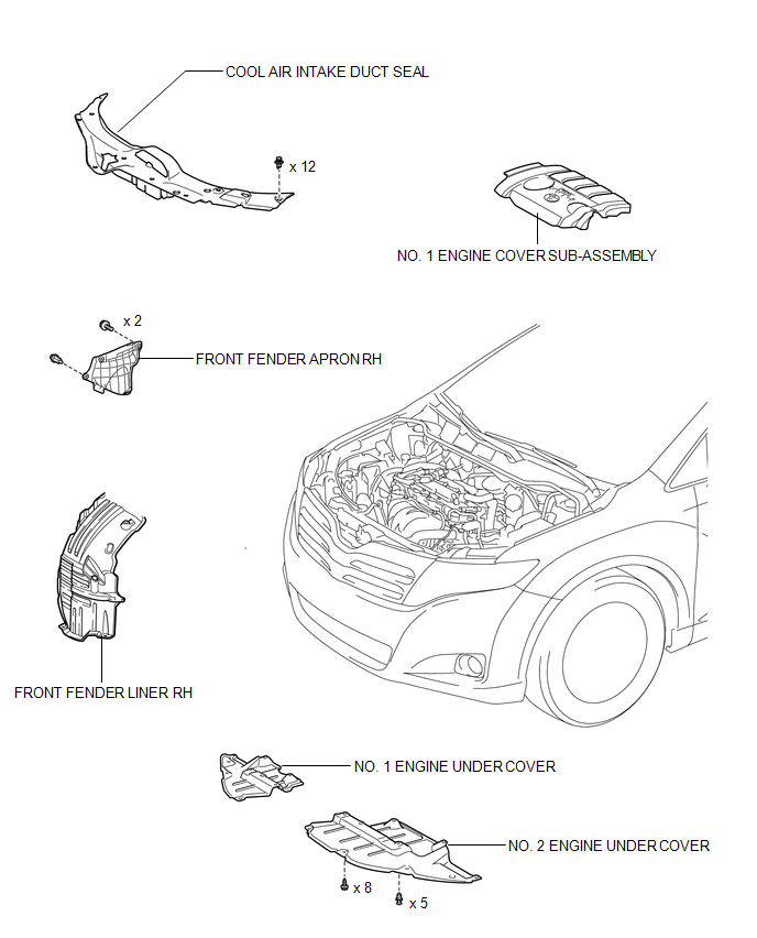
ILLUSTRATION
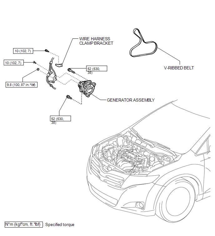
ILLUSTRATION
ILLUSTRATION
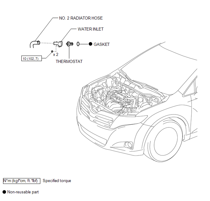
 Thermostat
...
 Removal
REMOVAL
PROCEDURE
1. DISCONNECT CABLE FROM NEGATIVE BATTERY TERMINAL
NOTICE:
When disconnecting the cable, some systems need to be initialized after the cable
is reconnected (See page ).
2. RE ...
Other materials about Toyota Venza:
Precaution
PRECAUTION
1. PRECAUTION FOR DISCONNECTING CABLE FROM NEGATIVE BATTERY TERMINAL
NOTICE:
When disconnecting the cable from the negative (-) battery terminal, initialize
the following system after the cable is reconnected.
System Name
...
Auxiliary boxes
►Type A (driver’s side instrument panel)
Push down the knob.
►Type B (front console)
Lift the lid.
►Type C (front console)
Lift the lid.
►Type D (front passenger’s side instrument
panel)
- Coin holder (type A) ...
Door Unlock Detection Switch Circuit
DESCRIPTION
The main body ECU (driver side junction block assembly) detects the condition
of the door unlock detection switch.
WIRING DIAGRAM
PROCEDURE
1.
READ VALUE USING TECHSTREAM
(a) Connect the Techstream to the DL ...

0.1509