Toyota Venza: Engine Immobiliser System Malfunction (B2799)
DESCRIPTION
This DTC is stored when one of the following occurs: 1) the ECM detects an error in its own communication with the certification ECU (smart key ECU assembly); 2) the ECM detects an error in the communication lines; or 3) the ECU communication ID between the certification ECU (smart key ECU assembly) and ECM is different when an engine start is attempted.
HINT:
Before troubleshooting this DTC, make sure that no certification ECU (smart key ECU assembly) DTCs are present. If present, troubleshoot the certification ECU (smart key ECU assembly) DTCs first.
|
DTC No. |
DTC Detection Condition |
Trouble Area |
|---|---|---|
|
B2799 |
One of the following conditions is met:
|
|
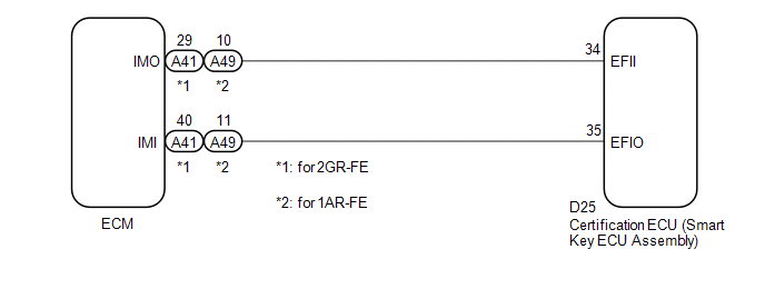
WIRING DIAGRAM
CAUTION / NOTICE / HINT
NOTICE:
If the certification ECU (smart key ECU assembly) is replaced, register the key
(See page .gif) ).
).
PROCEDURE
|
1. |
CHECK DTC OUTPUT |
(a) Clear the DTCs (See page ).
(b) Recheck for DTCs (See page ).
OK:
DTC B2799 is not output.
| OK | .gif) |
USE SIMULATION METHOD TO CHECK |
|
.gif)
|
2. |
RE-REGISTER ECU COMMUNICATION ID |
(a) Re-register the ECU communication ID (See page
).
|
|
3. |
CHECK DTC OUTPUT |
(a) Clear the DTCs (See page ).
(b) Recheck for DTCs (See page ).
OK:
DTC B2799 is not output.
| OK | |
END (ECU COMMUNICATION ID WAS INCORRECT) |
|
|
4. |
CHECK CONNECTOR CONNECTION CONDITION |
(a) Turn the engine switch off.
(b) Check that the connectors are properly connected to the ECM and certification ECU (smart key ECU assembly).
OK:
Connectors are properly connected.
| NG | |
CONNECT CONNECTORS PROPERLY |
|
|
5. |
CHECK HARNESS AND CONNECTOR (CERTIFICATION ECU - ECM) |
(a) Disconnect the certification ECU (smart key ECU assembly) connector.
|
(b) Disconnect the ECM connector. |
|
(c) Measure the resistance according to the value(s) in the table below.
Standard Resistance:
for 2GR-FE|
Tester Connection |
Condition |
Specified Condition |
|---|---|---|
|
D25-34 (EFII) - A41-29 (IMO) |
Always |
Below 1 Ω |
|
D25-35 (EFIO) - A41-40 (IMI) |
Always |
Below 1 Ω |
|
D25-34 (EFII) - Body ground |
Always |
10 kΩ or higher |
|
D25-35 (EFIO) - Body ground |
Always |
10 kΩ or higher |
|
Tester Connection |
Condition |
Specified Condition |
|---|---|---|
|
D25-34 (EFII) - A49-10 (IMO) |
Always |
Below 1 Ω |
|
D25-35 (EFIO) - A49-11 (IMI) |
Always |
Below 1 Ω |
|
D25-34 (EFII) - Body ground |
Always |
10 kΩ or higher |
|
D25-35 (EFIO) - Body ground |
Always |
10 kΩ or higher |
|
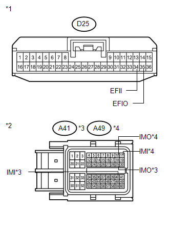
*1 |
Front view of wire harness connector (to Certification ECU (Smart Key ECU Assembly)) |
|
*2 |
Front view of wire harness connector (to ECM) |
|
*3 |
for 2GR-FE |
|
*4 |
for 1AR-FE |
| NG | |
REPAIR OR REPLACE HARNESS OR CONNECTOR |
|
|
6. |
REPLACE ECM |
(a) Replace the ECM (See page for 2GR-FE,
for 1AR-FE).
|
|
7. |
CHECK DTC OUTPUT |
(a) Clear the DTCs (See page ).
(b) Recheck for DTCs (See page ).
OK:
DTC B2799 is not output.
| OK | |
END (ECM WAS DEFECTIVE) |
| NG | |
REPLACE CERTIFICATION ECU (SMART KEY ECU ASSEMBLY) |
 Short to GND in Immobiliser System Power Source Circuit (B278A)
DESCRIPTION
This DTC is stored when the engine switch power source supply line is open or
shorted.
DTC No.
DTC Detection Condition
Trouble Area
B2 ...
 Antenna Coil Open / Short (B2784)
DESCRIPTION
This DTC is stored when there is an open or short in the transponder key coil
(built into the engine switch).
DTC No.
DTC Detection Condition
Trouble A ...
Other materials about Toyota Venza:
System Description
SYSTEM DESCRIPTION
1. PUSH-BUTTON START DESCRIPTION
(a) The push-button start uses a push-type engine switch, which the driver can
operate by merely carrying the electrical key. This system consists primarily of
the power management control ECU, engine s ...
Gauges and meters
►Vehicles with smart key system
The following gauges, meters and display illuminate when the “ENGINE START STOP”
switch is in IGNITION ON mode.
►Vehicles without smart key system
The following gauges, meters and displays illuminate when ...
System Diagram
SYSTEM DIAGRAM
Communication Table
Sender
Receiver
Signal
Communication Line
A/C amplifier
ECM
Magnetic clutch request signal*1
CAN
Idle up reques ...

0.1697