Toyota Venza: On-vehicle Inspection
ON-VEHICLE INSPECTION
PROCEDURE
1. CHECK RADIATOR CAP SUB-ASSEMBLY
(a) Measure the valve opening pressure.
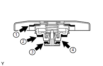
(1) If there are water stains or foreign matter on rubber packings 1, 2 or 3, clean the part(s) with water and finger scouring.
(2) Check that rubber packings 1, 2 and 3 are not deformed, cracked or swollen.
(3) Check that 3 and 4 are not stuck together.
(4) Apply engine coolant to rubber packings 2 and 3 before using the radiator cap tester.
|
(5) When using the cap tester, tilt it to 30° or more above level. |
|
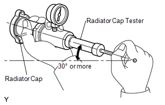
(6) Pump the cap tester several times, and check the maximum pressure*.
Pump speed:
1 pump per second
*: Even if the cap cannot maintain the maximum pressure, it is not a defect.
Judgment Criterion:
|
Item |
Specified Condition |
|---|---|
|
Standard value (for brand-new cap) |
94 to 122 kPa (1.0 to 1.2 kgf/cm2, 13.6 to 17 psi) |
|
Minimum standard value (for used cap) |
79 kPa (0.8 kgf/cm2, 11.4 psi) |
If the measured maximum pressure is less than the minimum standard value, replace the radiator cap sub-assembly.
 Components
COMPONENTS
ILLUSTRATION
ILLUSTRATION
ILLUSTRATION
...
 Installation
INSTALLATION
PROCEDURE
1. INSTALL RADIATOR ASSEMBLY
(a) Install the fan assembly with motor to the radiator with the 2 guides
at the bottom and 3 snap fits on the top.
Text in Ill ...
Other materials about Toyota Venza:
Removal
REMOVAL
PROCEDURE
1. REMOVE COOL AIR INTAKE DUCT SEAL
(a) Using a clip remover, remove the 12 clips and cool air intake duct
seal.
2. REMOVE RADIATOR GRILLE
3. REMOVE FRONT BUMPER ASSEMBLY
...
Differential System
Precaution
PRECAUTION
Before disassembly, clean the outside of the differential assembly and
remove any sand or mud to prevent it from entering the inside of the assembly
during disassembly and installation.
When removing an installed pa ...
How To Proceed With Troubleshooting
CAUTION / NOTICE / HINT
HINT:
The wireless door lock control system troubleshooting procedures are
based on the premise that the power door lock control system is operating
normally. Check the power door lock control system first before troub ...

0.1346