Toyota Venza: Removal
REMOVAL
PROCEDURE
1. PRECAUTION (w/ Navigation System)
NOTICE:
After turning the ignition switch off, waiting time may be required before disconnecting
the cable from the negative (-) battery terminal. Therefore, make sure to read the
disconnecting the cable from the negative (-) battery terminal notices before proceeding
with work (See page .gif) ).
).
2. DISCONNECT CABLE FROM NEGATIVE BATTERY TERMINAL (w/ Navigation System)
NOTICE:
When disconnecting the cable, some systems need to be initialized after the cable
is reconnected (See page ).
3. REMOVE UPPER CONSOLE PANEL SUB-ASSEMBLY (w/o Seat Heater System)
4. REMOVE UPPER CONSOLE PANEL SUB-ASSEMBLY (w/ Seat Heater System)
5. REMOVE NO. 2 CONSOLE BOX CARPET
6. REMOVE CONSOLE BOX ASSEMBLY
7. REMOVE AIR CONDITIONING CONTROL ASSEMBLY
8. REMOVE FRONT DOOR SCUFF PLATE RH
9. REMOVE COWL SIDE TRIM SUB-ASSEMBLY RH
10. REMOVE NO. 2 INSTRUMENT PANEL UNDER COVER SUB-ASSEMBLY
11. REMOVE LOWER INSTRUMENT PANEL SUB-ASSEMBLY
12. REMOVE SHIFT LEVER KNOB SUB-ASSEMBLY
13. REMOVE POSITION INDICATOR HOUSING ASSEMBLY
14. REMOVE CONSOLE BOX SUB-ASSEMBLY
15. REMOVE NO. 2 INSTRUMENT PANEL SPEAKER PANEL SUB-ASSEMBLY
16. REMOVE RADIO AND DISPLAY RECEIVER ASSEMBLY WITH BRACKET (w/o Navigation System)
17. REMOVE NAVIGATION RECEIVER ASSEMBLY WITH BRACKET (w/ Navigation System)
18. REMOVE INSTRUMENT CLUSTER CENTER FINISH PANEL SUB-ASSEMBLY (w/o Navigation System)
19. REMOVE INSTRUMENT CLUSTER CENTER FINISH PANEL SUB-ASSEMBLY (w/ Navigation System)
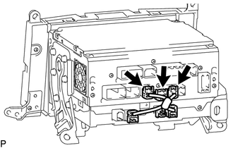
20. REMOVE STEREO COMPONENT TUNER ASSEMBLY WITH WIRE
|
(a) Disconnect the 3 connectors. |
|
|
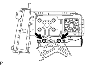
(b) Remove the 2 screws. |
|
|
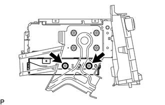
(c) Remove the 2 screws and stereo component tuner assembly with wire. |
|
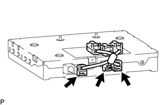
21. REMOVE NAVIGATION WIRE
|
(a) Disconnect the 3 connectors to remove the navigation wire. |
|
22. REMOVE STEREO COMPONENT TUNER ASSEMBLY
 Components
COMPONENTS
ILLUSTRATION
ILLUSTRATION
ILLUSTRATION
...
 Installation
INSTALLATION
PROCEDURE
1. INSTALL STEREO COMPONENT TUNER ASSEMBLY
2. INSTALL NAVIGATION WIRE
(a) Connect the 3 connectors to install the navigation wire.
3. INSTALL STEREO COMPONENT TUNER ASSEMBL ...
Other materials about Toyota Venza:
Abbreviations Used In Manual
ABBREVIATIONS USED IN MANUAL
Abbreviation
Meaning
ABS
Anti-Lock Brake System
A/C
Air Conditioner
AC
Alternating Current
ACC
A ...
Precaution
PRECAUTION
1. BASIC REPAIR HINT
(a) HINTS ON OPERATIONS
1
Attire
Always wear a clean uniform.
A hat and safety shoes must be worn.
2
Vehicle protection
Prep ...
How To Use This Manual
General Information
GENERAL INFORMATION
1. GENERAL DESCRIPTION
(a) This manual is written in accordance with SAE J2008.
(b) Repair operations can be separated mainly into the following 3 processes:
(1) Diagnosis
(2) Removing / Installing, Replacing, Di ...

0.1294