Toyota Venza: Components
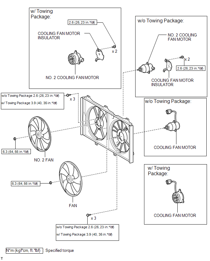
COMPONENTS
ILLUSTRATION

 On-vehicle Inspection
ON-VEHICLE INSPECTION
PROCEDURE
1. INSPECT COOLING FAN MOTOR
(a) Check that the motor operates smoothly when the battery is connected
to the cooling fan motor connector.
Text in I ...
Other materials about Toyota Venza:
Horn Circuit
DESCRIPTION
When the theft deterrent system is switched from the armed state to the alarm
sounding state, the main body ECU (driver side junction block assembly) transmits
a signal to cause the horn to sound at intervals of 0.4 seconds.
WIRING DIAGRAM
...
Center Airbag Sensor Communication Stop Mode
DESCRIPTION
Detection Item
Symptom
Trouble Area
Center Airbag Sensor Communication Stop Mode
"SRS Airbag" is not displayed on "CAN Bus Check" screen of the
Techs ...
If the engine will not start
If the engine still does not start after following the correct starting procedure
(, 175) or releasing the steering lock (, 176), confirm the following points.
- The engine will not start even if you are carrying the correct key.
One of the followi ...

0.1337